导读
在图像处理中,我们经常需要对图像进行各种操作如平移、缩放、旋转、翻转等,这些其实都是图像的仿射变换。通过本篇文章,你能够知道它们的实现原理以及如何应用它们。
仿射变换
仿射变换也称仿射投影,是指几何中,对一个向量空间进行线性变换并接上一个平移,变换为另一个向量空间。所以,仿射变换其实也就是再讲如何来进行两个向量空间的变换
假设有一个向量空间 k k k:
k = ( x , y ) k=(x,y) k=(x,y)
还有一个向量空间 j j j:
j = ( x ′ , y ′ ) j=(x’,y’) j=(x′,y′)
如果我们想要将向量空间由 k k k变为 j j j,可以通过下面的公式进行变换
j = k ∗ w + b j = k* w + b j=k∗w+b
将上式进行拆分可得
x ′ = w 00 ∗ x + w 01 ∗ y + b 0 y ′ = w 10 ∗ x + w 11 ∗ y + b 1 x’=w_{00}*x+w_{01}*y+b_0 \\ y’=w_{10}*x+w_{11}*y+b_1 x′=w00∗x+w01∗y+b0y′=w10∗x+w11∗y+b1
我们再将上式转换为矩阵的乘法
[ x ′ y ′ ] = [ w 00 w 01 b 0 w 10 w 11 b 1 ] [ x y 1 ] = M [ x y 1 ] (3) \left[ \begin{matrix} x’ \\ y’ \\ \end{matrix} \right] \tag{3}= \left[ \begin{matrix} w_{00} & w_{01} & b_0 \\ w_{10} & w_{11} & b_1\\ \end{matrix} \right] \left[ \begin{matrix} x \\ y \\ 1 \end{matrix} \right]= M \left[ \begin{matrix} x\\ y\\ 1 \end{matrix} \right] [x′y′]=[w00w10w01w11b0b1]⎣⎡xy1⎦⎤=M⎣⎡xy1⎦⎤(3)
通过参数矩阵 M M M就可以实现两个向量空间之间的转换,在进行仿射变换的时候我们也只需要一个矩阵 M M M就可以实现平移、缩放、旋转和翻转变换。
接下来,会先介绍原理然后利用OpenCV来实现相应的例子,这里主要利用OpenCV的warpAffine函数来实现仿射变换
warpAffine函数参数:
src:输入的图像数组M:仿射变换矩阵dsize:变换后图像的大小flags:使用的插值算法borderValue:边界的填充值
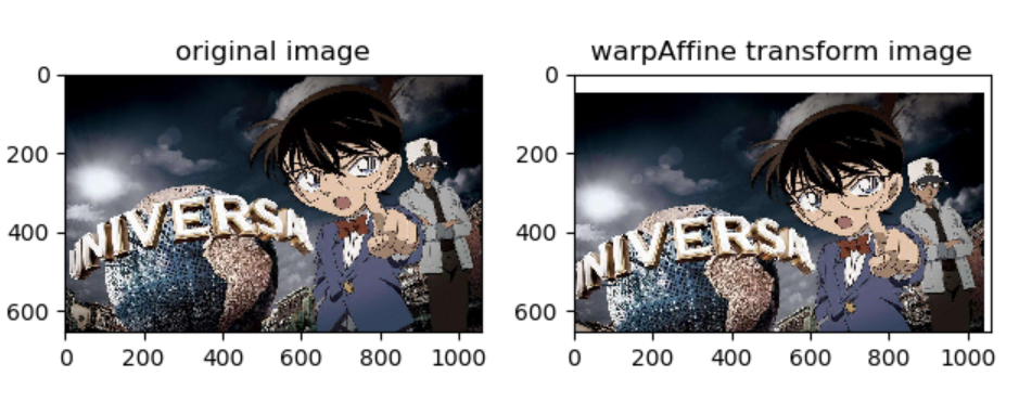
图像平移
在平面坐标系有点 P ( x , y ) P(x,y) P(x,y)和点 P ′ ( x ′ , y ′ ) P'(x’,y’) P′(x′,y′),如果我们想要将 P P P点移动到 P ′ P’ P′通过下面的变换就可以实现
x ′ = x + Δ x y ′ = y + Δ y x’=x+\Delta x \\ y’ = y + \Delta y x′=x+Δxy′=y+Δy
其中 Δ x \Delta x Δx和 Δ y \Delta y Δy就是x方向上和y方向上的偏移量,我们将其转换为矩阵的形式
[ x ′ y ′ ] = [ 1 0 Δ x 0 1 Δ y ] [ x y 1 ] = M [ x y 1 ] \left[ \begin{matrix} x’\\ y’\\ \end{matrix} \right]= \left[ \begin{matrix} 1 & 0 & \Delta x\\ 0 & 1 & \Delta y\\ \end{matrix} \right] \left[ \begin{matrix} x\\ y\\ 1 \end{matrix} \right]= M\left[ \begin{matrix} x\\ y\\ 1 \end{matrix} \right] [x′y′]=[1001ΔxΔy]⎣⎡xy1⎦⎤=M⎣⎡xy1⎦⎤
上面的矩阵 M M M就是仿射变换的平移参数,接下来我们利用OpenCV中的warpAffine函数来实现
import cv2
import numpy as np
import matplotlib.pyplot as plt

def show_compare_img(original_img,transform_img):
    _,axes = plt.subplots(1,2)
    #显示图像
    axes[0].imshow(original_img)
    axes[1].imshow(transform_img)
    #设置子标题
    axes[0].set_title("original image")
    axes[1].set_title("warpAffine transform image")
    plt.show()


def translation_img():
    # 定义一个图像平移矩阵
    # x向左平移(负数向左,正数向右)20个像素
    # y向下平移(负数向上,正数向下)50个像素
    M = np.array([[1, 0, -20], [0, 1, 50]], dtype=np.float)
    # 读取需要平移的图像
    img = cv2.imread("test.jpg")
    # 将图片由BGR转为RGB
    img = cv2.cvtColor(img, cv2.COLOR_BGR2RGB)
    # 定义平移后图像的大小,保持和原图大小一致
    dsize = img.shape[:2][::-1]
    # 便于大家观察这里采用白色来填充边界
    translation_img = cv2.warpAffine(img, M, dsize, borderValue=(255, 255, 255))
    # 显示图像
    show_compare_img(img, translation_img)

translation_img()
图像翻转
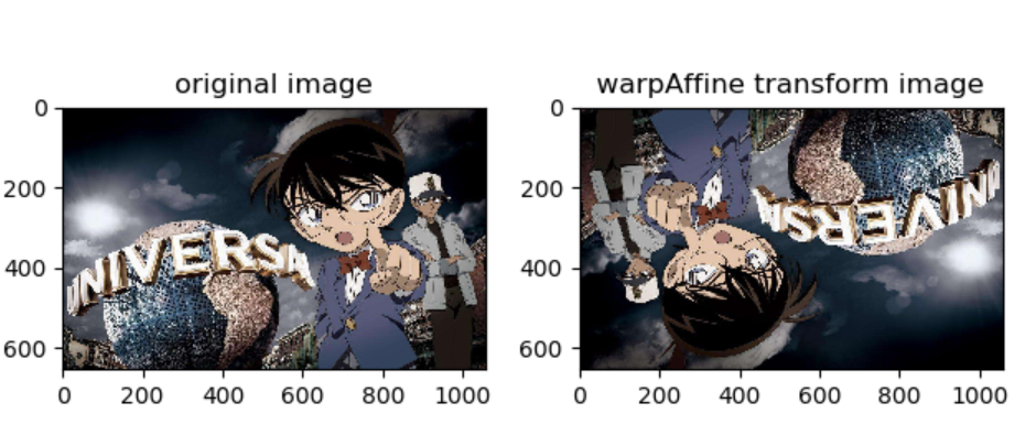
有时候我们我们需要对图像进行水平翻转、垂直翻转、镜像翻转(同时进行水平和垂直翻转),想要实现这个功能并不难,我们可以通过opencv内置的flip方法很容易实现,还可以通过numpy的索引来实现,这里我们主要介绍通过仿射变换矩阵来实现这个功能
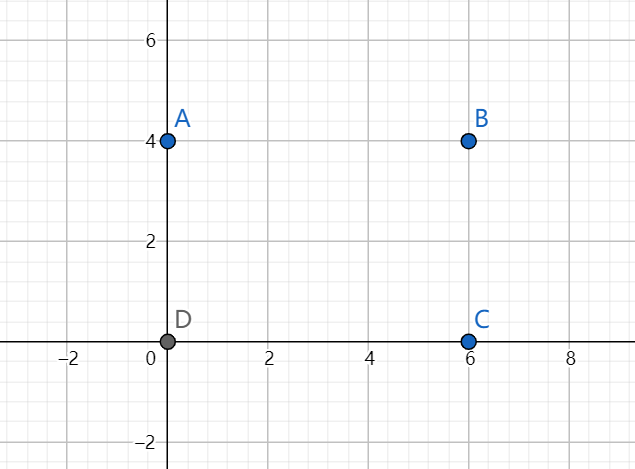
上图中的 A 、 B 、 C 、 D A、B、C、D A、B、C、D表示图像的四个顶点,如果我们需要对图像进行水平翻转,那么我们就需要将 A A A点和 B B B点进行交换, C C C点和 D D D点进行交换,沿着x轴的中线进行对称交换位置,通过下面的式子可以实现水平翻转
x ′ = − x + w \begin{aligned} x’ = -x + w \end{aligned} x′=−x+w
上式中的 w w w表示图像的宽,同理可得垂直翻转的实现公式
y ′ = − y + h \begin{aligned} y’ = -y + h \end{aligned} y′=−y+h
上式中的 h h h表示的是图像的高
- 变换矩阵翻转图像
图像翻转的变换矩阵
水 平 翻 转 的 变 换 矩 阵 : M = [ − 1 0 w 0 1 0 ] 垂 直 翻 转 的 变 换 矩 阵 : M = [ 1 0 0 0 − 1 h ] 镜 像 变 换 的 矩 阵 : M = [ − 1 0 w 0 − 1 h ] \begin{aligned} 水平翻转的变换矩阵:\\ M=\left[ \begin{matrix} -1 & 0 & w\\ 0 & 1 & 0\\ \end{matrix} \right]\\ 垂直翻转的变换矩阵:\\ M=\left[ \begin{matrix} 1 & 0 & 0\\ 0 & -1 & h\\ \end{matrix} \right]\\ 镜像变换的矩阵:\\ M=\left[ \begin{matrix} -1 & 0 & w\\ 0 & -1 & h\\ \end{matrix} \right] \end{aligned} 水平翻转的变换矩阵:M=[−1001w0]垂直翻转的变换矩阵:M=[100−10h]镜像变换的矩阵:M=[−100−1wh]
def flip_img(horizontal_flip,vertical_flip,img):
    #获取输入图片的宽和高
    height,width = img.shape[:2]
    #初始化变换矩阵
    M = np.array([[0, 0, 0], [0, 0, 0]], dtype=np.float)
    #水平翻转
    if horizontal_flip:
        M[0] = [-1,0,width]
    #垂直翻转
    if vertical_flip:
        M[1] = [0,-1,height]
    # 将图片由BGR转为RGB
    img = cv2.cvtColor(img, cv2.COLOR_BGR2RGB)
    # 定义缩放后图片的大小
    img_flip = cv2.warpAffine(img, M, (width,height))
    # 显示图像
    show_compare_img(img, img_flip)

img = cv2.imread("test.jpg")
flip_img(True,True,img)
- OpenCV的flip函数翻转图像
flip函数参数:
src:输入的图像数组flipCode:图像翻转参数,1表示水平翻转,0表示垂直翻转,-1表示镜像翻转
img = cv2.imread("test.jpg")
#水平翻转
horizontal_flip_img = cv2.flip(img,1)
#垂直翻转
vertical_flip_img = cv2.flip(img,0)
#镜像翻转
mirror_flip_img = cv2.flip(img,-1)
- numpy的索引翻转图像
img = cv2.imread("test.jpg")
#水平翻转
horizontal_flip_img = img[:,::-1]
#垂直翻转
vertical_flip_img = img[::-1]
#镜像翻转
mirror_flip_img = img[::-1,::-1]
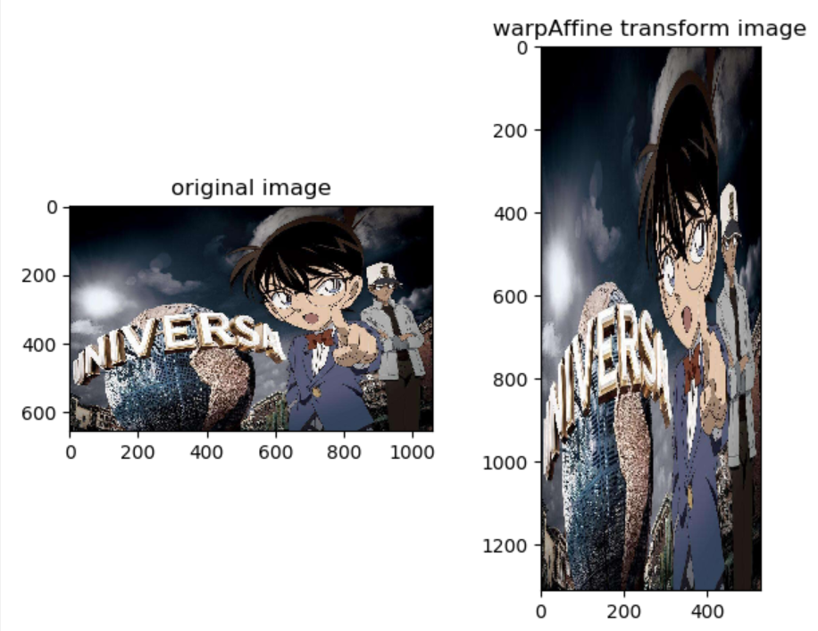
图像缩放
如果我们想要对坐标系的 P P P点进行缩放操作,通过下面的公式就可以实现
x ′ = f x ∗ x y ′ = f y ∗ y x’=f_x * x\\ y’=f_y * y x′=fx∗xy′=fy∗y
通过,在 x x x和 y y y前面添加一个缩放系数即可,同样我们将其转换为矩阵形式
[ x ′ y ′ ] = [ f x 0 0 0 f y 0 ] [ x y 1 ] = M [ x y 1 ] \left[ \begin{matrix} x’\\ y’\\ \end{matrix} \right]= \left[ \begin{matrix} f_x & 0 & 0\\ 0 & f_y & 0\\ \end{matrix} \right] \left[ \begin{matrix} x\\ y\\ 1 \end{matrix} \right]= M\left[ \begin{matrix} x\\ y\\ 1 \end{matrix} \right] [x′y′]=[fx00fy00]⎣⎡xy1⎦⎤=M⎣⎡xy1⎦⎤
通过上面的矩阵 M M M我们就可以实现对图片的缩放
def scale_img():
    #定义宽缩放的倍数
    fx = 0.5
    #定义高缩放的倍数
    fy = 2
    #定义一个图像缩放矩阵
    M = np.array([[fx,0,0],[0,fy,0]],dtype=np.float)
    #读取图像
    img = cv2.imread("test.jpg")
    #获取图片的宽和高
    height,width = img.shape[:2]
    #将图片由BGR转为RGB
    img = cv2.cvtColor(img,cv2.COLOR_BGR2RGB)
    #定义缩放后图片的大小
    scale_img = cv2.warpAffine(img,M,(int(width*fx),int(height*fy)))
    #显示图像
    show_compare_img(img,scale_img)

scale_img()
这里使用仿射变换实现的图像缩放其实和resize函数的效果是一样的
图像旋转
- 围绕原点旋转
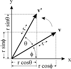
我们先来看看一个二维平面上的点在围绕原点是如何旋转的
上图中点 v v v在围绕原点旋转 θ \theta θ度之后得到了点 v ′ v’ v′,我们将坐标点用极坐标的形式来表示可以得到 v ( r c o s ϕ , r s i n ϕ ) v(rcos\phi,rsin\phi) v(rcosϕ,rsinϕ),所以 v ′ ( r c o s ( θ + ϕ ) , r s i n ( θ + ϕ ) ) v'(rcos(\theta+\phi),rsin(\theta+\phi)) v′(rcos(θ+ϕ),rsin(θ+ϕ))利用正弦和余弦将其展开可得
对 于 v 点 来 说 : x = r c o s ϕ y = r s i n ϕ 对 于 v ′ 来 说 : x ′ = r c o s ( θ + ϕ ) = r c o s θ ∗ c o s ϕ − r s i n θ ∗ s i n ϕ y ′ = r s i n ( θ + ϕ ) = r s i n θ ∗ c o s ϕ + r c o s θ ∗ s i n ϕ 然 后 再 将 x 和 y 代 入 上 式 , 可 得 x ′ = x ∗ c o s θ − y ∗ s i n θ y ′ = x ∗ s i n θ + y ∗ c o s θ \begin{aligned} 对于v点来说:\\ & x = rcos\phi\\ & y = rsin\phi \\ 对于v’来说:\\ x’ &= rcos(\theta+\phi) \\ &=r cos\theta * cos\phi – r sin\theta * sin\phi \\ y’ &= rsin(\theta+\phi) \\ &= rsin\theta*cos\phi + rcos\theta * sin\phi \\ 然后再将x和y代入上式,可得 \\ x’ &= x * cos\theta-y*sin\theta \\ y’ &= x * sin\theta + y * cos\theta \\ \end{aligned} 对于v点来说:对于v′来说:x′y′然后再将x和y代入上式,可得x′y′x=rcosϕy=rsinϕ=rcos(θ+ϕ)=rcosθ∗cosϕ−rsinθ∗sinϕ=rsin(θ+ϕ)=rsinθ∗cosϕ+rcosθ∗sinϕ=x∗cosθ−y∗sinθ=x∗sinθ+y∗cosθ
然后再将上式用矩阵 M M M表示,可得
[ x ′ y ′ ] = [ c o s θ − s i n θ 0 s i n θ c o s θ 0 ] [ x y 1 ] = M [ x y 1 ] \left[ \begin{matrix} x’\\ y’\\ \end{matrix} \right]= \left[ \begin{matrix} cos\theta & -sin\theta & 0\\ sin\theta & cos\theta & 0\\ \end{matrix} \right] \left[ \begin{matrix} x\\ y\\ 1 \end{matrix} \right]= M\left[ \begin{matrix} x\\ y\\ 1 \end{matrix} \right] [x′y′]=[cosθsinθ−sinθcosθ00]⎣⎡xy1⎦⎤=M⎣⎡xy1⎦⎤
特别注意:我们在建立直角坐标系的时候是以左下角为原点建立的,然而对于图像而言是以左上角为原点建立的,所以我们需要对角度 θ \theta θ进行取反,结合三角函数的特性, M M M矩阵的表达式如下
M = [ c o s θ s i n θ 0 − s i n θ c o s θ 0 ] M= \left[ \begin{matrix} cos\theta & sin\theta & 0\\ -sin\theta & cos\theta & 0\\ \end{matrix} \right] M=[cosθ−sinθsinθcosθ00]
还需要注意的是这里的角度都是弧度制,所以我们还需要对其进行转换,转换代码如下
#将角度转换为弧度制
radian_theta = theta/180 * np.pi
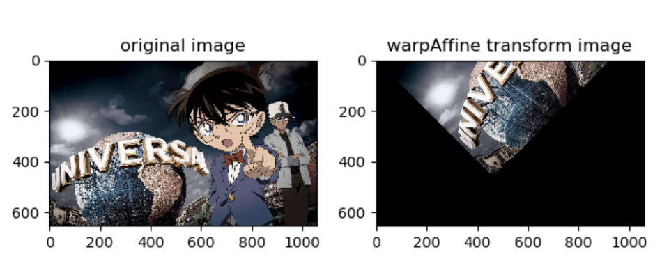
将图片围绕原点进行逆时针旋转 θ \theta θ度的代码如下
def rotate_img_original(theta):
   #将角度转换为弧度制
   radian_theta = theta/180 * np.pi
   #定义围绕原点旋转的变换矩阵
   M = np.array([[np.cos(radian_theta),np.sin(radian_theta),0],
                 [-np.sin(radian_theta),np.cos(radian_theta),0]])
   # 读取图像
   img = cv2.imread("test.jpg")
   #定义旋转后图片的宽和高
   height,width = img.shape[:2]
   # 将图片由BGR转为RGB
   img = cv2.cvtColor(img, cv2.COLOR_BGR2RGB)
   #围绕原点逆时针旋转\theta度
   rotate_img = cv2.warpAffine(img,M,(width,height))
   #显示图像
   show_compare_img(img,rotate_img)
rotate_img_original(45)
- 围绕任意点旋转
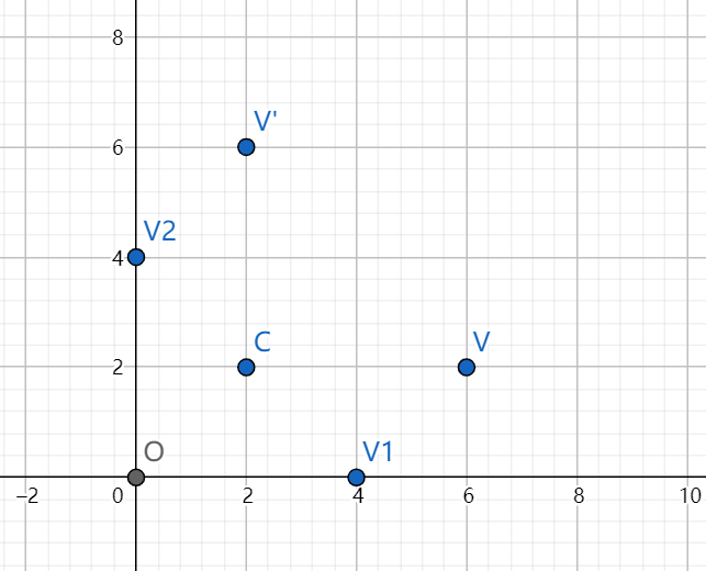
如果我们想围绕任意坐标点旋转呢?其实也并不难,下图的v点在围绕 c c c点 ( a , b ) (a,b) (a,b)旋转90度得到 v ′ v’ v′。其实我们可以将其等价于,先将 v v v点平移到 v 1 v_1 v1点,然后再将 v 1 v_1 v1点围绕原点旋转90度得到 v 2 v_2 v2点,最后再将 v 2 v_2 v2点沿着 v v v点平移的反方向平移相同长度,最终得到 v ′ v’ v′。这样我们就将围绕任意坐标点旋转的问题转换成了围绕原点旋转的问题
我们来回顾一下,围绕原点旋转坐标的变换公式:
x ′ = x ∗ c o s θ − y ∗ s i n θ y ′ = x ∗ s i n θ + y ∗ c o s θ \begin{aligned} x’ &= x * cos\theta-y*sin\theta \\ y’ &= x * sin\theta + y * cos\theta \\ \end{aligned} x′y′=x∗cosθ−y∗sinθ=x∗sinθ+y∗cosθ
在围绕原点旋转变换公式的基础上,我们将其改进为围绕任意点 c ( a , b ) c(a,b) c(a,b)旋转,我们现在原来的坐标进行平移,得到变换后的坐标,最后再沿着之前平移的反方向进行平移,就得到围绕任意点旋转的变换公式:
x ′ = ( x − a ) ∗ c o s θ − ( y − b ) ∗ s i n θ + a y ′ = ( x − a ) ∗ s i n θ + ( y − b ) ∗ c o s θ + b \begin{aligned} x’ &= (x-a) * cos\theta-(y-b)*sin\theta + a \\ y’ &= (x-a) * sin\theta + (y-b) * cos\theta + b \\ \end{aligned} x′y′=(x−a)∗cosθ−(y−b)∗sinθ+a=(x−a)∗sinθ+(y−b)∗cosθ+b
将其展开可得
x ′ = x ∗ c o s θ − y ∗ s i n θ + ( 1 − c o s θ ) ∗ a + b ∗ s i n θ y ′ = x ∗ s i n θ + y ∗ c o s θ + ( 1 − c o s θ ) ∗ b − a ∗ s i n θ \begin{aligned} x’ &= x*cos\theta – y * sin\theta + (1-cos\theta)*a + b * sin\theta\\ y’ &= x*sin\theta + y * cos\theta + (1-cos\theta)*b – a*sin\theta\\ \end{aligned} x′y′=x∗cosθ−y∗sinθ+(1−cosθ)∗a+b∗sinθ=x∗sinθ+y∗cosθ+(1−cosθ)∗b−a∗sinθ
将上式用矩阵 M M M表示:
[ x ′ y ′ ] = [ c o s θ − s i n θ ( 1 − c o s θ ) ∗ a + b ∗ s i n θ s i n θ c o s θ ( 1 − c o s θ ) ∗ b − a ∗ s i n θ ] [ x y 1 ] = M [ x y 1 ] \left[ \begin{matrix} x’\\ y’\\ \end{matrix} \right]= \left[ \begin{matrix} cos\theta & -sin\theta & (1-cos\theta)*a + b * sin\theta\\ sin\theta & cos\theta & (1-cos\theta)*b – a*sin\theta\\ \end{matrix} \right] \left[ \begin{matrix} x\\ y\\ 1 \end{matrix} \right]= M\left[ \begin{matrix} x\\ y\\ 1 \end{matrix} \right] [x′y′]=[cosθsinθ−sinθcosθ(1−cosθ)∗a+b∗sinθ(1−cosθ)∗b−a∗sinθ]⎣⎡xy1⎦⎤=M⎣⎡xy1⎦⎤
上式中的c(a,b)表示旋转中心,因为坐标系问题需要对 θ \theta θ进行取反,最终 M M M矩阵的表达式如下
M = [ c o s θ s i n θ ( 1 − c o s θ ) ∗ a − b ∗ s i n θ − s i n θ c o s θ ( 1 − c o s θ ) ∗ b + a ∗ s i n θ ] M=\left[ \begin{matrix} cos\theta & sin\theta & (1-cos\theta)*a – b * sin\theta\\ -sin\theta & cos\theta & (1-cos\theta)*b + a*sin\theta\\ \end{matrix} \right] M=[cosθ−sinθsinθcosθ(1−cosθ)∗a−b∗sinθ(1−cosθ)∗b+a∗sinθ]
def rotate_img_point(point_x,point_y,theta,img):
    #将角度转换为弧度制
    radian_theta = theta / 180 * np.pi
    #定义围绕任意点旋转的变换矩阵
    M = np.array([[np.cos(radian_theta), np.sin(radian_theta),
                   (1-np.cos(radian_theta))*point_x-point_y*np.sin(radian_theta)],
                  [-np.sin(radian_theta), np.cos(radian_theta),
                   (1-np.cos(radian_theta))*point_y+point_x*np.sin(radian_theta)]])
    # 将图片由BGR转为RGB
    img = cv2.cvtColor(img, cv2.COLOR_BGR2RGB)
    # 定义旋转后图片的宽和高
    height, width = img.shape[:2]
    # 围绕原点逆时针旋转\theta度
    rotate_img = cv2.warpAffine(img, M, (width, height))
    # 显示图像
    show_compare_img(img, rotate_img)

img = cv2.imread("test.jpg")
height,width = img.shape[:2]
#定义围绕图片的中心旋转
point_x,point_y = int(width/2),int(height/2)
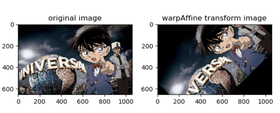
rotate_img_point(point_x,point_y,45,img)
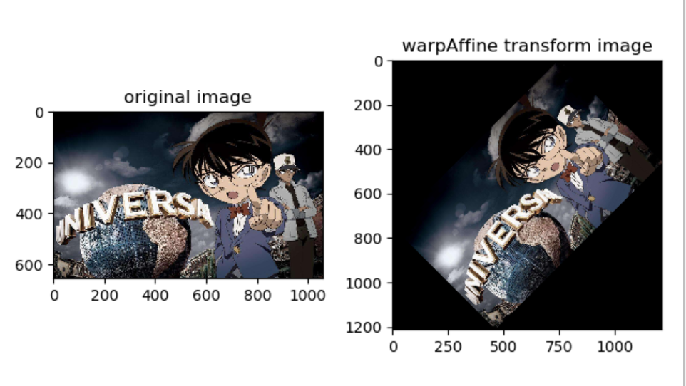
细心的同学也许已经发现了,上图中围绕图像中心旋转后的图片部分被裁剪掉了,如果我们想让旋转之后的图片仍然是完整,应该如何修改呢?
def rotate_img_point(point_x,point_y,theta,img,is_completed=False):
    #将角度转换为弧度制
    radian_theta = theta / 180 * np.pi
    #定义围绕任意点旋转的变换矩阵
    M = np.array([[np.cos(radian_theta), np.sin(radian_theta),
                   (1-np.cos(radian_theta))*point_x-point_y*np.sin(radian_theta)],
                  [-np.sin(radian_theta), np.cos(radian_theta),
                   (1-np.cos(radian_theta))*point_y+point_x*np.sin(radian_theta)]])
    # 将图片由BGR转为RGB
    img = cv2.cvtColor(img, cv2.COLOR_BGR2RGB)
    # 定义旋转后图片的宽和高
    height, width = img.shape[:2]
    #判断旋转之后的图片是否需要保持完整
    if is_completed:
        #增大旋转之后图片的宽和高,防止被裁剪掉
        new_height = height * np.cos(radian_theta) + width * np.sin(radian_theta)
        new_width = height * np.sin(radian_theta) + width * np.cos(radian_theta)
        #增大变换矩阵的平移参数
        M[0, 2] += (new_width - width) * 0.5
        M[1, 2] += (new_height - height) * 0.5
        height = int(np.round(new_height))
        width = int(np.round(new_width))
    # 围绕原点逆时针旋转\theta度
    rotate_img = cv2.warpAffine(img, M, (width, height))
    # 显示图像
    show_compare_img(img, rotate_img)

img = cv2.imread("test.jpg")
height,width = img.shape[:2]
#定义围绕图片的中心旋转
point_x,point_y = int(width/2),int(height/2)
rotate_img_point(point_x,point_y,45,img,True)
今天的文章一文搞懂仿射变换分享到此就结束了,感谢您的阅读。
版权声明:本文内容由互联网用户自发贡献,该文观点仅代表作者本人。本站仅提供信息存储空间服务,不拥有所有权,不承担相关法律责任。如发现本站有涉嫌侵权/违法违规的内容, 请发送邮件至 举报,一经查实,本站将立刻删除。
如需转载请保留出处:https://bianchenghao.cn/4912.html

