1. 插件的添加
在相应的<joint>标签内添加如下代码:
        <sensor name="force_torque" type="force_torque">
          <update_rate>30</update_rate>
        </sensor>
运行world:
gazebo --verbose force_torque_tutorial.world
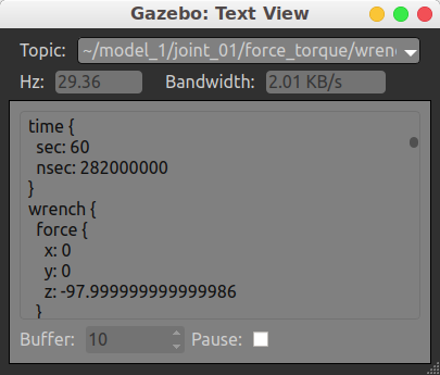
查看传感器输出:
- 法1:命令查看
gz topic --view /gazebo/default/model_1/joint_01/force_torque/wrench - 法2:Ctrl+T
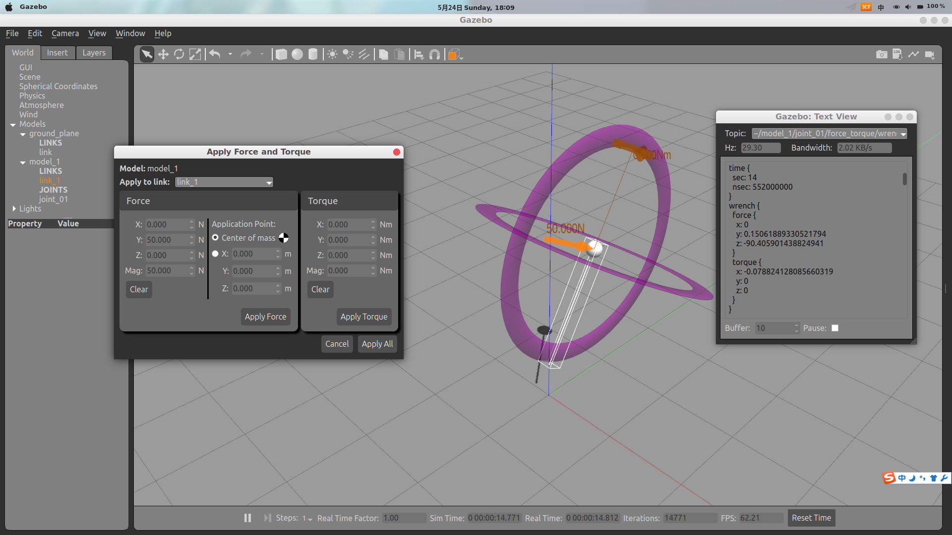
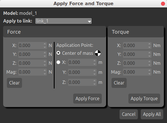
添加一个力,测试仿真情况,并观察力/力矩输出情况:
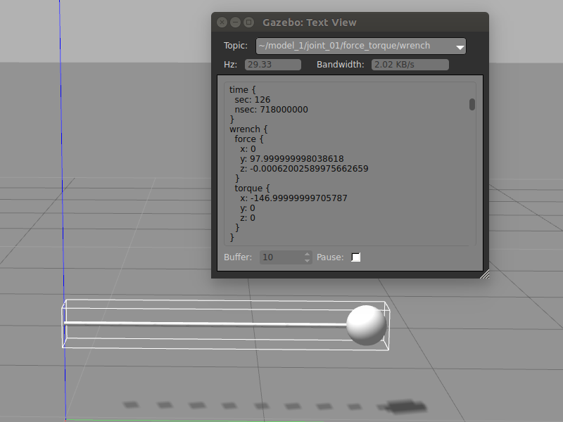
倾倒以后,受力情况如下:
已知球体质量为10kg,距离关节1.5m,开始时只受重力影响:
forceJointZ = mass * g
            = 10 kg * -9.8 m/s^2
            = -98 N
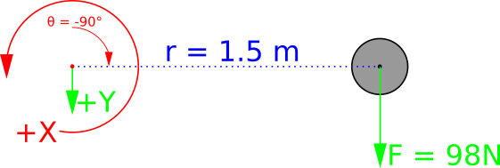
给y方向施加500N,倾倒90°后,关节+Y轴指向地面,作用在球体上的重力会绕X轴施加扭矩:
torqueJoint01_x = r X R
                = ||r|| * ||F|| * sin(theta)
                = distanceZ * (massLink * g) * sin(theta)
                = 1.5 m * (10 kg * 9.8 m/s^2) * sin(-90)
                = -147 Nm
注意:根据物理引擎参数,接近关节极限的测量值可能会发生跳跃!问题叙述参见https://github.com/osrf/gazebo/issues/2209
力/力矩的添加:
参见Apping Force/Torque
2. SDF参数说明
传感器通用参数:
SDF传感器架构参见-http://sdformat.org/spec?ver=1.6&elem=sensor
<always_on>:如果为true,则传感器始终测量力/力矩;如果为false,则仅在有订阅者连接到传感器主题的情况下传感器才会更新;通过代码访问传感器时,此设置很重要;如果没有订阅者,则调用ForceTorqueSensor::Torque()或ForceTorqueSensor::Force()将返回旧数据;可以通过检查是否返回来检测;代码可以通过调用来更新没有订阅者的传感器。<update_rate>:传感器更新频率(Hz),即传感器每秒发布的消息数<visualize>:如果为true,则Gazebo client将对关节处的力/力矩进行可视化<topic>:力/扭矩传感器当前不支持该参数<frame>:力/扭矩传感器当前不支持该参数<pose>:浮点数,用空格分隔x y z roll pitch yaw,它描述了传感器坐标系相对于父关节的位置
ForceTorqueSensor Class头文件为#include <sensors/sensors.hh>
ForceTorque特定参数:
<sensor name="my_cool_sensor" type="force_torque">
  <force_torque>
    <frame>child</frame>
    <measure_direction>child_to_parent</measure_direction>
  </force_torque>
</sensor>
通过添加属性类型设置为force_torque的<sensor>标签来创建力/扭矩传感器,可以设置两个附加参数:
-
<frame>:其值有三种,child、parent、sensor;其表示力/力矩坐标系,parent和child用于指定关节哪端是父节点哪端是子节点(即可用来设置旋转方向???),sensor值意味着测量值是通过该传感器的<pose>的旋转分量描述的,姿势的平移分量对测量没有影响。无论此设置如何,扭矩分量始终以关节坐标系的原点表示。
-
<measure_direction>:测量方向,尝试将上面的例子改为parent_to_child,倾倒以后会发现,传感器测量值在Y轴上的力为-98 N,在X轴上的扭矩为+147 Nm,数值与以前相同,但方向相反。
3. 说明
- 尽管SDF允许将
<sensor>标签放置在link或joint上,但ForceTorqueSensor仅在关节上起作用。如果将传感器添加到link,则使用--verbose运行gazebo时会报错:
[Err] [Link.cc:114] A link cannot load a [force_torque] sensor.
-
以上示例将力/力矩传感器放置在旋转关节上,但是实际情况中力/力矩传感器通常被刚性地安装在另一个刚体上,真实传感器无法准确测量旋转关节起点处的力/力矩。
① 如果实际传感器距离关节足够近,以至于偏移误差可忽略,则这种方式建模是合理的;
② 如果该误差不可忽略,可以在实际传感器的位置处通过固定关节将刚体分成两个joint
4. 示例sdf文件
<?xml version="1.0"?>
<sdf version="1.6">
  <world name="default">
    <physics name="default_physics" default="0" type="ode">
      <max_step_size>0.001</max_step_size>
      <real_time_factor>1</real_time_factor>
      <real_time_update_rate>1000</real_time_update_rate>
      <ode>
        <solver>
          <type>quick</type>
          <iters>50</iters>
          <sor>1.0</sor> <!-- Important, see issue #2209 -->
          <use_dynamic_moi_rescaling>false</use_dynamic_moi_rescaling>
        </solver>
      </ode>
    </physics>
    <include>
      <uri>model://ground_plane</uri>
    </include>
    <include>
      <uri>model://sun</uri>
    </include>
    <model name="model_1">
      <link name="link_1">
        <pose>0 0 2.0 0 0 0</pose>
        <inertial>
          <inertia>
            <ixx>0.100000</ixx>
            <ixy>0.000000</ixy>
            <ixz>0.000000</ixz>
            <iyy>0.100000</iyy>
            <iyz>0.000000</iyz>
            <izz>0.100000</izz>
          </inertia>
          <mass>10.000000</mass>
        </inertial>
        <visual name="visual_sphere">
          <geometry>
            <sphere>
              <radius>0.100000</radius>
            </sphere>
          </geometry>
        </visual>
        <visual name="visual_cylinder">
          <pose>0 0 -0.75 0 0 0</pose>
          <geometry>
            <cylinder>
              <radius>0.0100000</radius>
              <length>1.5</length>
            </cylinder>
          </geometry>
        </visual>
        <collision name="collision_sphere">
          <max_contacts>250</max_contacts>
          <geometry>
            <sphere>
              <radius>0.100000</radius>
            </sphere>
          </geometry>
        </collision>
      </link>
      <joint name="joint_01" type="revolute">
        <parent>world</parent>
        <child>link_1</child>
        <pose>0 0 -1.5 0 0 0</pose>
        <axis>
          <limit>
            <lower>-1.57079</lower>
            <upper>1.57079</upper>
          </limit>
          <dynamics>
            <damping>0.000000</damping>
            <friction>0.000000</friction>
          </dynamics>
          <xyz>1.000000 0.000000 0.000000</xyz>
        </axis>
        <sensor name="force_torque" type="force_torque">
          <update_rate>30</update_rate>
        </sensor>
      </joint>
    </model>
  </world>
</sdf>
参考文献:
今天的文章Gazebo使用笔记(5) —— 力/力矩传感器的使用分享到此就结束了,感谢您的阅读。
版权声明:本文内容由互联网用户自发贡献,该文观点仅代表作者本人。本站仅提供信息存储空间服务,不拥有所有权,不承担相关法律责任。如发现本站有涉嫌侵权/违法违规的内容, 请发送邮件至 举报,一经查实,本站将立刻删除。
如需转载请保留出处:https://bianchenghao.cn/5432.html

