
ATMega328PB-AU烧录bootloader探索研究
- 📍本论坛的相关烧录教程(通过一块Arduino UNO板作为ISP来烧录的)《为ATMega328pb芯片烧录Arduino bootloader》,或者参考《用Arduino UNO作为AVR ISP烧录器 烧bootloader(引导程序)》
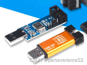
- 📌USBasp个人相关内容《2018版USBASP烧录器改通用版教》
- 📘ATMega328PB和ATMega328P差异中文说明文档资料:
链接:https://pan.baidu.com/s/1aPofMTCNnOTwvggppaNHlQ?pwd=xtax
提取码:xtax
- 📍原文文档:https://ww1.microchip.com/downloads/en/AppNotes/Atmel-42559-Differences-between-ATmega328P-and-ATmega328PB_ApplicationNote_AT15007.pdf
- ✨本文是通过USBasp工具进行Bootloader烧录的。

- ✨本文使用ATMega328PB-AU烧录bootloader作为研究测试对象。
- 🎉bootloader目的:为了摆脱单一的ISP烧录方式,实现串口烧录。
- 👉烧录bootloader前提,必须要有一个AVR烧录器或者Arduino UNO/nano开发板。
- 🌿当前Arduino IDE环境下,支持
ATMega328PB芯片型号的支持包固件:ATMega328PB支持包网址:
https://files.pololu.com/arduino/package_pololu_index.json
https://mcudude.github.io/MiniCore/package_MCUdude_MiniCore_index.json
- 📌熔丝位在线计算网站,适用于AVR系列单片机:
https://www.engbedded.com/fusecalc/ - 📌熔丝位在线配置网站,适用于AVR系列单片机:
https://www.engbedded.com/conffuse/
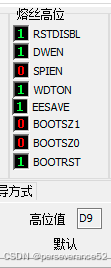
🛠boot loader熔丝位配置
- 影响Boot Loader Parameters主要是高熔丝:

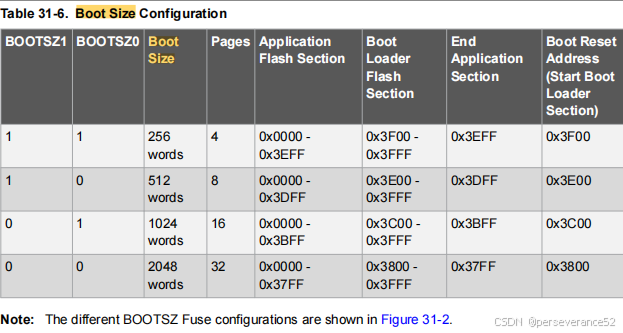
- 🌿BOOTLOADER区大小配置位:
BOOTSZ1和BOOTSZ0:这两位确定了BOOTLOADER区的大小以及其起始的首地址。默认的状态为“00”,
- 🌿
BOOTRST: 复位向量地址选择。
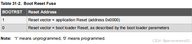
✨决定MCU上电时,第一条执行指令的地址。默认状态为“1”,表示起动时从0x0000开始执行。如果BOOTRST设置为“0”,则起动时从BOOTLOADER区的起始地址处开始执行程序。BOOTLOADER区的大小由
BOOTSZ1和BOOTSZ0决定,因此其首地址也随之变化。
- 🌟如果芯片里面烧写了bootloader程序,并想要复位后从引导区开始,就需要配置此位0。
- 🔖具体信息可以参考328PB手册31章:
BTLDR - Boot Loader Support – Read-While-Write Self-Programming内容。
-
🈯烧录bootloader的目的:为了方便在Arduino IDE开发环境下,使用串口烧录程序。需要依赖
bootloader固件+串口,才能完成代码上传的工作。如果手上有AVR烧录器,那么可以通过AVR烧录器+烧录软件,完成程序烧录即可。 -
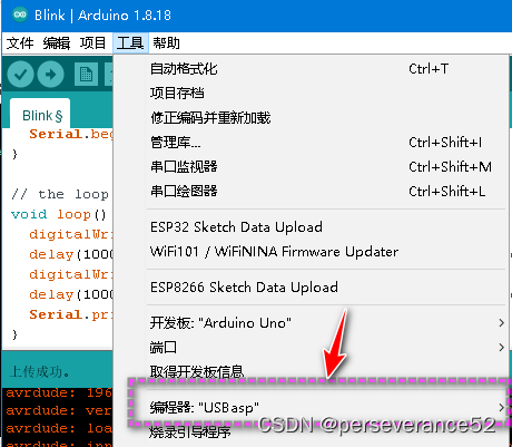
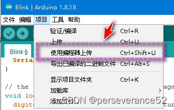
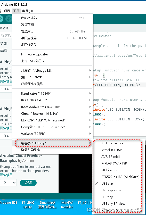
如果使用USBasp 直接上传代码,在Arduino IDE直接选择
USBasp进行代码上传。
📑前言
趁目前
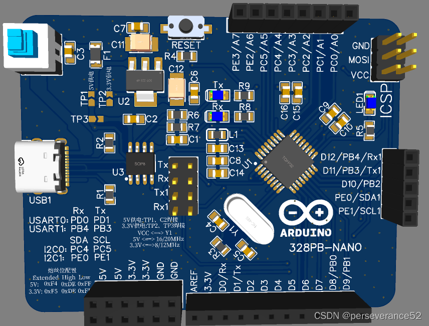
ATMega328PB-AU主控芯片的价格比较便宜,购买了一片此型号芯片,刚刚完成ATMega328PB-AU主控的开发板的设计,准备打板,先测试下一是否兼容Arduino nano开发板,于是将手上现有的Arduino nano板子上的32引脚TQFP封装的ATMega328P更换了下来,换上ATMega328PB-AU进行bootloader烧录。

- 📌PCB开源链接:
https://oshwhub.com/perseverance51/atmega328pb-au-nano
📘bootloader和串口外围参考电路
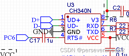
- 🔰芯片的 RST复位引脚需要接入到USB转串口芯片的Mode联络信号引脚上,这里以CH340N为例,芯片的复位引脚通过一个耦合电容接到CH340N的RST引脚上。
🌟bootloader固件选择
-
🔰
ATMega328PB如果选择使用MiniCore固件所提供的Bootloader烧录文件,之后使用Arduino IDE程序上传都需要选择此类型的开发板的对应型号,并不能选择其他支持包下面的同型号芯片进行上传。采用不同支持包下的bootloader固件,下载算法有些差异。。(MiniCore支持包,还提供了使用串口1(PB4/PB3)作为烧录口的选择方式)。
-
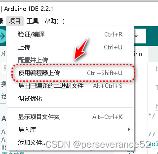
- 👉如果选择使用编程器上传程序,就不存在上面的情况。只需要型号正确,就可以上传代码。需要注意一点的是,一旦选择了编程器上传代码,会导致原来芯片上,已下载过的bootloader程序段失效,下次下载程序,将不能再次使用串口直接上传程序。
-
- 📄MiniCore:
"C:\Users\Administrator\AppData\Local\Arduino15\packages\MiniCore\tools\avrdude\7.2-arduino.1/bin/avrdude" "-CC:\Users\Administrator\AppData\Local\Arduino15\packages\MiniCore\hardware\avr\3.0.1/avrdude.conf" -v -patmega328pb -curclock -PCOM9 -b9600 -D -xnometadata "-Ueeprom:w:C:\Users\Administrator\AppData\Local\Temp\arduino\sketches\D21CF4E415C37110D46815DADA9CBA76/Blink.ino.eep:i" "-Uflash:w:C:\Users\Administrator\AppData\Local\Temp\arduino\sketches\\D21CF4E415C37110D46815DADA9CBA76/Blink.ino.hex:i""
- 在MiniCore固件支持包下包含有非常多不同参数的bootloader程序,方便单独烧录:
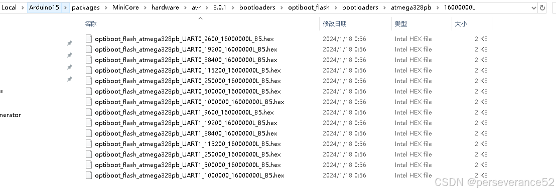
-
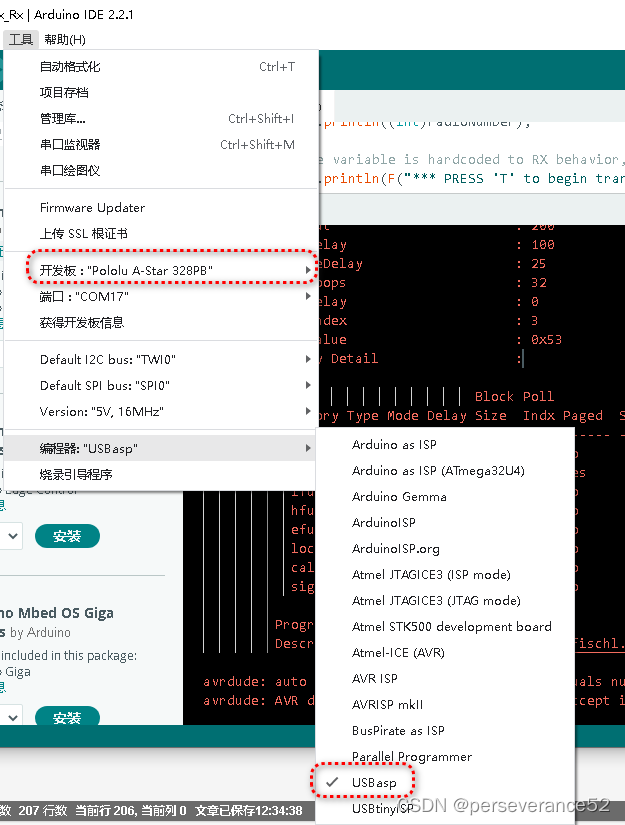
- 📄Polulo:
"C:\Users\Administrator\AppData\Local\Arduino15\packages\arduino\tools\avrdude\6.3.0-arduino17/bin/avrdude" "-CC:\Users\Administrator\AppData\Local\Arduino15\packages\arduino\tools\avrdude\6.3.0-arduino17/etc/avrdude.conf" -v -patmega328pb -carduino "-PCOM9" -b115200 -D "-Uflash:w:C:\Users\Administrator\AppData\Local\Temp\arduino\sketches\D21CF4E415C37110D46815DADA9CBA76/Blink.ino.hex:i"
-👉 如果使用独立的烧录软件,通过加载编译好的Hex文件进行烧录不存在此问题。
- 🏷当然
ATMega328PB不仅仅限于以上2个固件开发板,还有其他的支持的固件支持包。
⛳熔丝设置错误修复
- 📍以下内容修复方法参考:
https://blog.csdn.net/gongqingkui/article/details/74180247
- 👉 新的Atmega328PB,如果因为熔丝位设置错误,导致无法编程、烧录器无法访问、工作比不正常,解决办法是用其它正常工作的晶振接入,挽救锁死的芯片。
- 🔖Atmega328PB 新片默认熔丝位 :
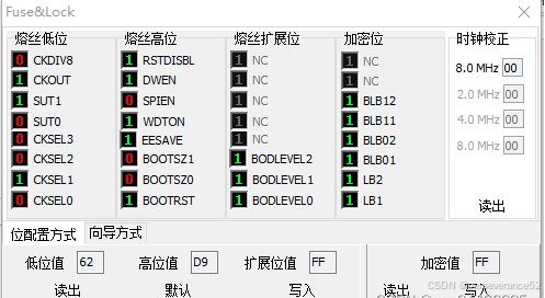
  Low High Extended

  0x62 0xd9 0xff
- 🔧用正常工作的使用外部晶振的单片机,例如STC89/12的XTAL2引脚,接入Atmega328PB的XTAL1(PB6)引脚,重新对Atmega328PB上电,就可以重新读入熔丝位了。重新写入默认熔丝位,就可以复原芯片了。
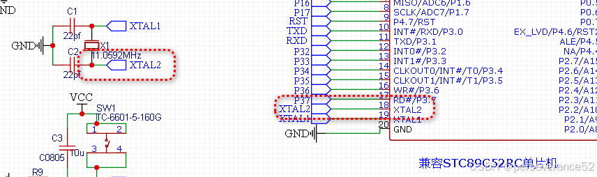
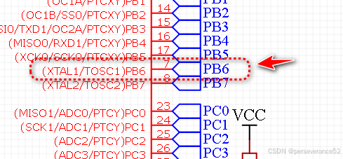
个人实测该方法真实有效,是就砖的好办法。
⚡注意事项
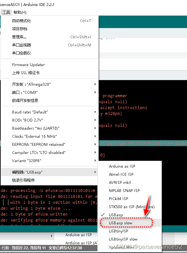
- 🌿新的未使用过的ATMega328PB-AU的芯片,在使用USBasp工具进行Arduino IDE在线 Bootloader烧录时,需要选择
USBasp slow才行,这一点很关键!!!个人在选择USBasp模式下,对从未使用过的新芯片,烧录了N多遍的失败经历,曾一度怀疑是不是芯片没有焊接好。
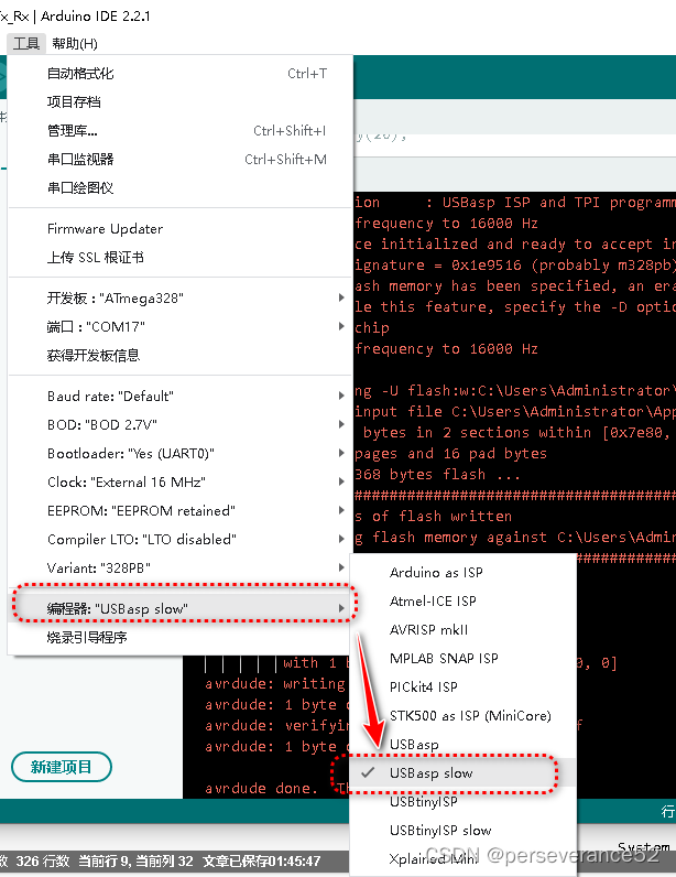
- 🔖在第一次选择
USBasp slow模式下,烧录成功后,后面如果有需要再次烧录bootloader程序,可以直接选择USBasp模式进行烧录。
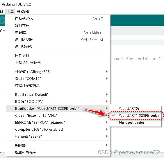
- ⚡
USBasp slow模式只有选择安装了MiniCore固件下才有,pololu固件不带,这一点需要注意!
- 🌿另外需要注意一点的是,刷的是哪个固件支持包的bootloader程序,在Arduino IDE 上传代码时,就只能选择对应系列的单片机型号,进行上传代码。(例如刷的是
MiniCore固件支持包所提供的bootloader程序,那么在使用Arduino IDE 开发时,烧录目标只能选择MiniCore下的对于型号才行,而不能选择pololu固件支持下的同芯片型号,不能通用)。如果使用独立的AVR第三方烧录工具,可以直接加载编译好的Hex文件除外。
🔱在没有bootloader程序的情况下程序烧录补充说明
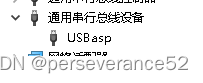
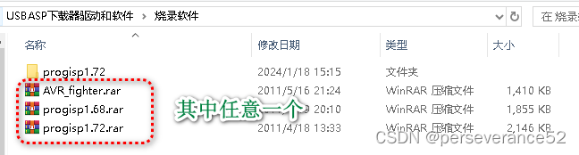
- 🌿使用其他AVR烧录软件:AVR_fighter、progisp、AVRDUDESS。(前提是手上需要有一个USBASP或者USBISP)。
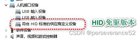
- 🔖经测试AVR_fighter连不上,progisp需要使用HID 免驱版本的USBasp烧录器使用,
不支持Arduino IDE在线烧录bootloader方式。USBASP带驱动版本的使用AVRDUDESS或者Arduino IDE在线烧录bootloader方式。
-
- 🔖带驱动版本的:
- 🔖带驱动版本的:
资料下载地址:http://pan.baidu.com/s/1i49UCOP
https://pan.baidu.com/s/1eTYTxp4
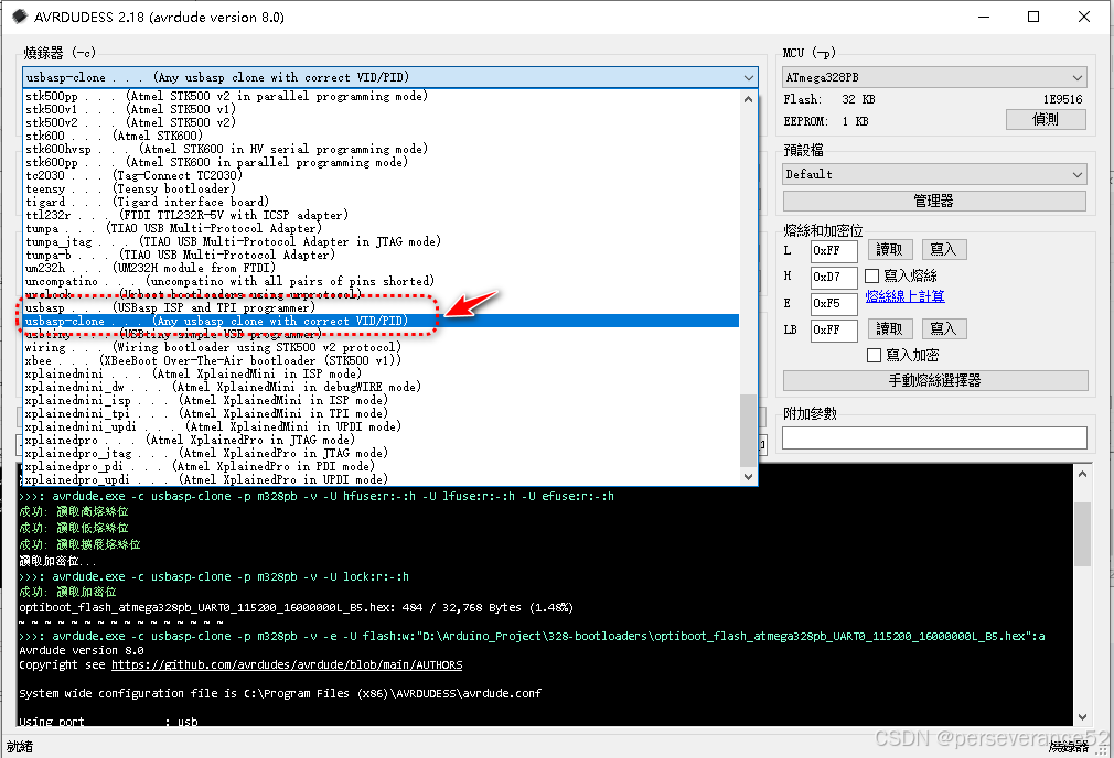
AVRDUDESS:下载地址:https://github.com/ZakKemble/AVRDUDESS/releases
Khazama AVR Programmer For USBasp and avrdude:http://khazama.com/project/programmer/
- avrdude:https://download.savannah.gnu.org/releases/avrdude/
- 🌿
AVRDUDESS:下载地址:https://github.com/ZakKemble/AVRDUDESS/releases
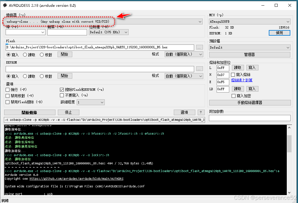
- 如果采用的是开源自制的USBASP的,那么在使用
AVRDUDESS工具进行固件烧录时,推荐选择:usbasp-clone
- usbasp驱动类型WinUSB和libsub参考说明:
https://electronics.stackexchange.com/questions/416714/avrdude-does-not-recognize-usbasp-device/417509#417509
on most places on the internet you will be instructed to install the libusbK driver, which doesn’t work, use the libusb-win32 variant instead
make sure the AVRDUDE.EXE tool is the latest version (the older doesn’t work with the newer USB drivers for some reason)
in case of using a clone (for instance having “Van Ooijen’s technische informatica” as vendor id instead of the original name “www.fischl.de”), make sure to use the -c usbasp-clone -P usb AVRDUDE settings instead of -c usbap -P usb. The clone setting causes AVRDUDE to ignore the vendor description and also accept the clone. You’d think having the correct VID, PID combination would be sufficient but no…
🌿Khazama AVR Programmer软件:经测试,该软件不支持ATMega328PB型号的程序烧录。
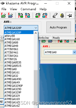
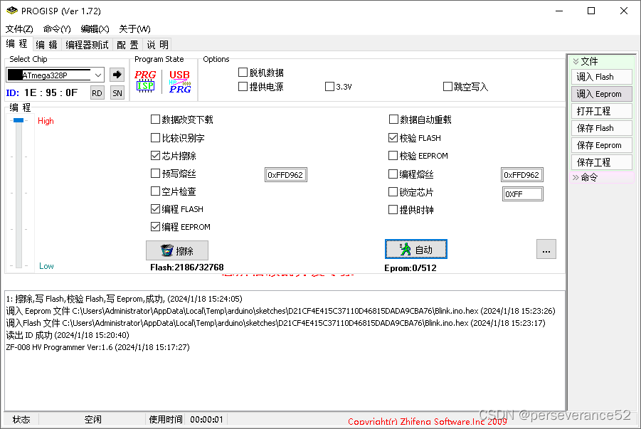
- 🌿使用progisp软件,烧录Arduino IDE编译好的Hex文件。(只能使用,市面上售卖的免驱版的USBasp使用,只能选择
ATMega328P来替代ATMega328PB)
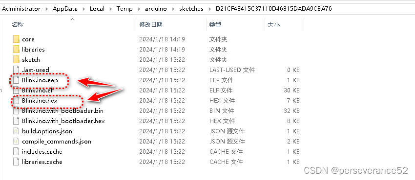
- 🔖上面.eep为EEPROM文件,.hex为程序文件。分别通过
调入Flash和调入Eeprom加载进来。
- 🌿如果想通过上面的软件顺便将带bootloader的文件烧录进去,可以选择类似
Blink.ino.with_bootloader.hex名称的合并文件。(bootloader和程序合并文件)
- 📌AVR单片机熔丝位设置详细知识文档介绍可以参考:https://www.cnblogs.com/Arrow-Lu/articles/2584823.html
- 👉如果烧录了带
bootloader程序文件后,配置好对于的串口端口号后,可以直接通过Arduino IDE面板上的上传按钮进行上传,即可,无需关注编程器选项。- 🔖如果目标板不带Bootloader程序的,那么只能选择对于的编程器,然后进行上传。
- 🌿如果直接加载文件烧录,可以从Arduino IDE 在已安装的支持包路径下找到
bootloader文件 -
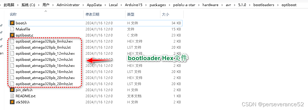
- 🔖🏷 pololu-a-star支持包下的
bootloader文件位置:
- 🔖🏷 pololu-a-star支持包下的
C:\Users\Administrator\AppData\Local\Arduino15\packages\pololu-a-star\hardware\avr\5.1.0\bootloaders\optiboot
-
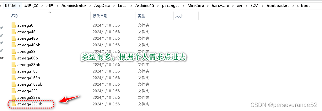
- 🔖🏷 MiniCore支持包下的
bootloader文件位置:
- 🔖🏷 MiniCore支持包下的
C:\Users\Administrator\AppData\Local\Arduino15\packages\MiniCore\hardware\avr\3.0.1\bootloaders\urboot
🛠烧录前准备
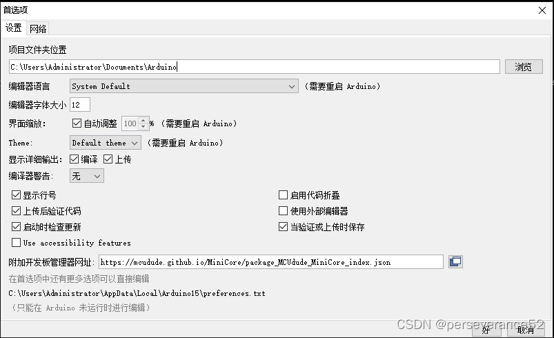
- 🌿给Arduino IDE安装支持芯片型
ATMega328PB开发板。 - 🌿添加网址:
https://mcudude.github.io/MiniCore/package_MCUdude_MiniCore_index.json - 🔖或者添加:
https://files.pololu.com/arduino/package_pololu_index.json
👉如果对新的芯片首次进行烧录,那么推荐先选择用
MiniCore固件,选择对应的单片机型号,进行烧录,因为可以选择USBasp slow慢速模式。
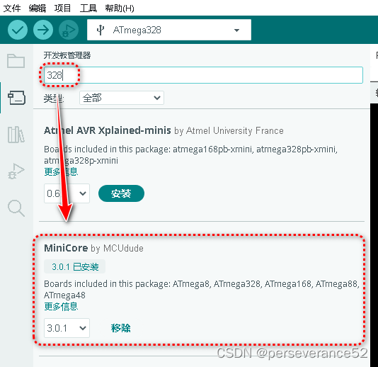
- 🌿搜索关键字
328,找到MiniCore固件进行安装。
- 🌿通过USBasp工具烧录配置信息如下:
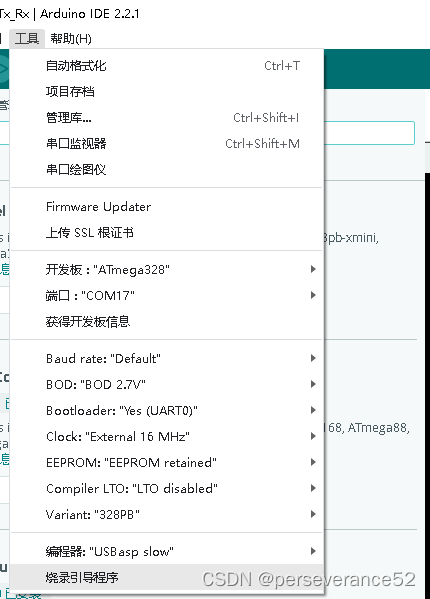
🈯USBasp工具烧录过程
- 📄经测试,通过Arduino IDE
1.8.1.x版本或者使用2.2.x版本,都是可以的。 - 📑通过USBasp工具进行烧录时的信息:
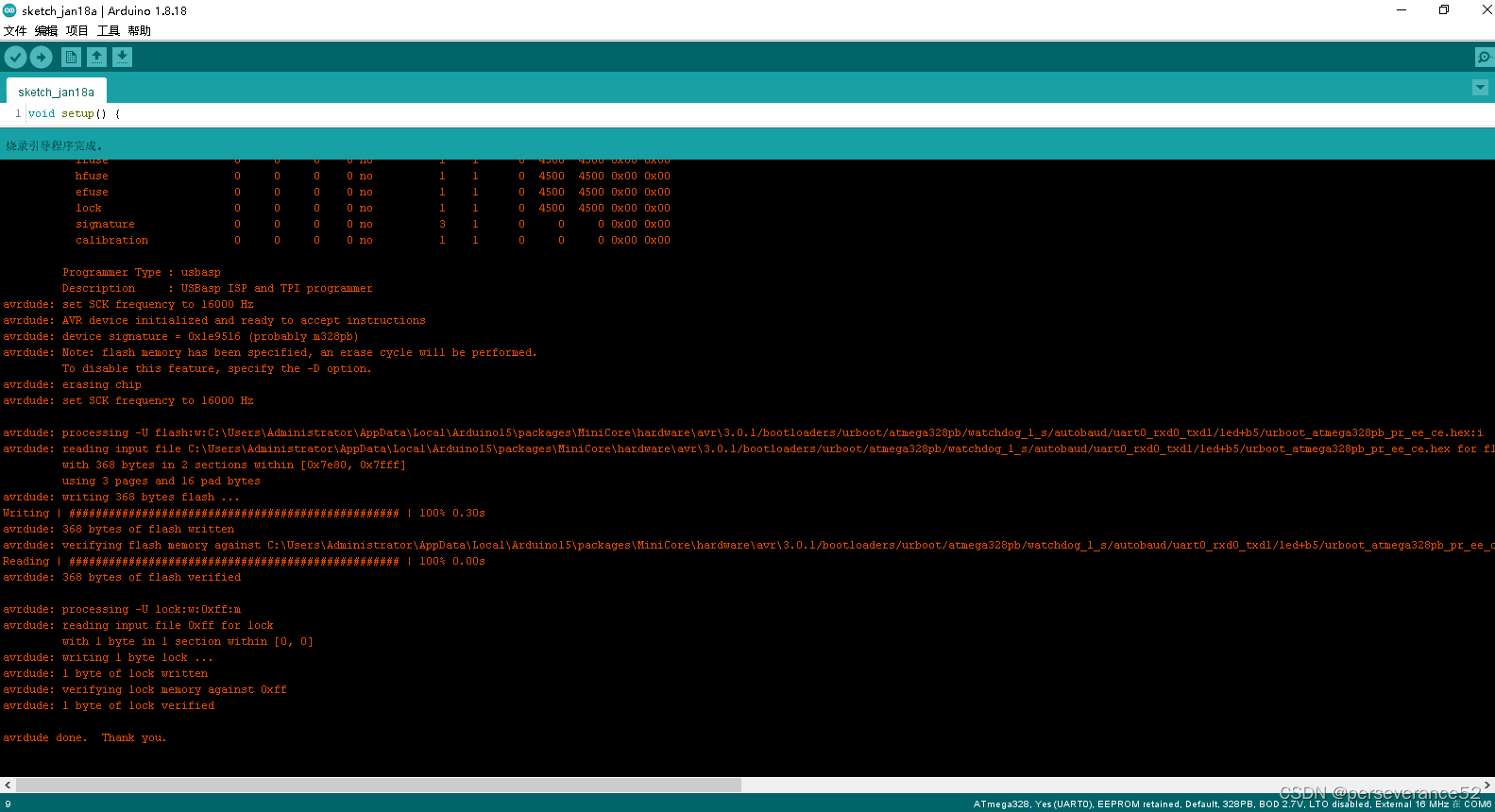
C:\Users\Administrator\AppData\Local\Arduino15\packages\MiniCore\tools\avrdude\7.2-arduino.1/bin/avrdude -CC:\Users\Administrator\AppData\Local\Arduino15\packages\MiniCore\hardware\avr\3.0.1/avrdude.conf -v -patmega328pb -cusbasp -B32 -e -Ulock:w:0xff:m -Uefuse:w:0b11110101:m -Uhfuse:w:0xd7:m -Ulfuse:w:0b11111111:m

avrdude: Version 7.2-arduino.1
         Copyright the AVRDUDE authors;
         see https://github.com/avrdudes/avrdude/blob/main/AUTHORS

         System wide configuration file is C:\Users\Administrator\AppData\Local\Arduino15\packages\MiniCore\hardware\avr\3.0.1\avrdude.conf

         Using Port                    : usb
         Using Programmer              : usbasp
         Setting bit clk period        : 32.0
         AVR Part                      : ATmega328PB
         Chip Erase delay              : 10500 us
         PAGEL                         : PD7
         BS2                           : PC2
         RESET disposition             : possible i/o
         RETRY pulse                   : SCK
         Serial program mode           : yes
         Parallel program mode         : yes
         Timeout                       : 200
         StabDelay                     : 100
         CmdexeDelay                   : 25
         SyncLoops                     : 32
         PollIndex                     : 3
         PollValue                     : 0x53
         Memory Detail                 :

                                           Block Poll               Page                       Polled
           Memory Type Alias    Mode Delay Size  Indx Paged  Size   Size #Pages MinW  MaxW   ReadBack
           ----------- -------- ---- ----- ----- ---- ------ ------ ---- ------ ----- ----- ---------
           eeprom                 65    20     4    0 no       1024    4      0  3600  3600 0x00 0x00
           flash                  65    10   128    0 yes     32768  128    256  4500  4500 0x00 0x00
           lfuse                   0     0     0    0 no          1    1      0  4500  4500 0x00 0x00
           hfuse                   0     0     0    0 no          1    1      0  4500  4500 0x00 0x00
           efuse                   0     0     0    0 no          1    1      0  4500  4500 0x00 0x00
           lock                    0     0     0    0 no          1    1      0  4500  4500 0x00 0x00
           signature               0     0     0    0 no          3    1      0     0     0 0x00 0x00
           calibration             0     0     0    0 no          1    1      0     0     0 0x00 0x00

         Programmer Type : usbasp
         Description     : USBasp ISP and TPI programmer
avrdude: set SCK frequency to 16000 Hz
avrdude: AVR device initialized and ready to accept instructions
avrdude: device signature = 0x1e9516 (probably m328pb)
avrdude: erasing chip
avrdude: set SCK frequency to 16000 Hz

avrdude: processing -U lock:w:0xff:m
avrdude: reading input file 0xff for lock
         with 1 byte in 1 section within [0, 0]
avrdude: writing 1 byte lock ...
avrdude: 1 byte of lock written
avrdude: verifying lock memory against 0xff
avrdude: 1 byte of lock verified

avrdude: processing -U efuse:w:0b11110101:m
avrdude: reading input file 0b11110101 for efuse
         with 1 byte in 1 section within [0, 0]
avrdude: writing 1 byte efuse ...
avrdude: 1 byte of efuse written
avrdude: verifying efuse memory against 0b11110101
avrdude: 1 byte of efuse verified

avrdude: processing -U hfuse:w:0xd7:m
avrdude: reading input file 0xd7 for hfuse
         with 1 byte in 1 section within [0, 0]
avrdude: writing 1 byte hfuse ...
avrdude: 1 byte of hfuse written
avrdude: verifying hfuse memory against 0xd7
avrdude: 1 byte of hfuse verified

avrdude: processing -U lfuse:w:0b11111111:m
avrdude: reading input file 0b11111111 for lfuse
         with 1 byte in 1 section within [0, 0]
avrdude: writing 1 byte lfuse ...
avrdude: 1 byte of lfuse written
avrdude: verifying lfuse memory against 0b11111111
avrdude: 1 byte of lfuse verified

avrdude done.  Thank you.

C:\Users\Administrator\AppData\Local\Arduino15\packages\MiniCore\tools\avrdude\7.2-arduino.1/bin/avrdude -CC:\Users\Administrator\AppData\Local\Arduino15\packages\MiniCore\hardware\avr\3.0.1/avrdude.conf -v -patmega328pb -cusbasp -B32 -Uflash:w:C:\Users\Administrator\AppData\Local\Arduino15\packages\MiniCore\hardware\avr\3.0.1/bootloaders/urboot/atmega328pb/watchdog_1_s/autobaud/uart0_rxd0_txd1/led+b5/urboot_atmega328pb_pr_ee_ce.hex:i -Ulock:w:0xff:m

avrdude: Version 7.2-arduino.1
         Copyright the AVRDUDE authors;
         see https://github.com/avrdudes/avrdude/blob/main/AUTHORS

         System wide configuration file is C:\Users\Administrator\AppData\Local\Arduino15\packages\MiniCore\hardware\avr\3.0.1\avrdude.conf

         Using Port                    : usb
         Using Programmer              : usbasp
         Setting bit clk period        : 32.0
         AVR Part                      : ATmega328PB
         Chip Erase delay              : 10500 us
         PAGEL                         : PD7
         BS2                           : PC2
         RESET disposition             : possible i/o
         RETRY pulse                   : SCK
         Serial program mode           : yes
         Parallel program mode         : yes
         Timeout                       : 200
         StabDelay                     : 100
         CmdexeDelay                   : 25
         SyncLoops                     : 32
         PollIndex                     : 3
         PollValue                     : 0x53
         Memory Detail                 :

                                           Block Poll               Page                       Polled
           Memory Type Alias    Mode Delay Size  Indx Paged  Size   Size #Pages MinW  MaxW   ReadBack
           ----------- -------- ---- ----- ----- ---- ------ ------ ---- ------ ----- ----- ---------
           eeprom                 65    20     4    0 no       1024    4      0  3600  3600 0x00 0x00
           flash                  65    10   128    0 yes     32768  128    256  4500  4500 0x00 0x00
           lfuse                   0     0     0    0 no          1    1      0  4500  4500 0x00 0x00
           hfuse                   0     0     0    0 no          1    1      0  4500  4500 0x00 0x00
           efuse                   0     0     0    0 no          1    1      0  4500  4500 0x00 0x00
           lock                    0     0     0    0 no          1    1      0  4500  4500 0x00 0x00
           signature               0     0     0    0 no          3    1      0     0     0 0x00 0x00
           calibration             0     0     0    0 no          1    1      0     0     0 0x00 0x00

         Programmer Type : usbasp
         Description     : USBasp ISP and TPI programmer
avrdude: set SCK frequency to 16000 Hz
avrdude: AVR device initialized and ready to accept instructions
avrdude: device signature = 0x1e9516 (probably m328pb)
avrdude: Note: flash memory has been specified, an erase cycle will be performed.
         To disable this feature, specify the -D option.
avrdude: erasing chip
avrdude: set SCK frequency to 16000 Hz

avrdude: processing -U flash:w:C:\Users\Administrator\AppData\Local\Arduino15\packages\MiniCore\hardware\avr\3.0.1/bootloaders/urboot/atmega328pb/watchdog_1_s/autobaud/uart0_rxd0_txd1/led+b5/urboot_atmega328pb_pr_ee_ce.hex:i
avrdude: reading input file C:\Users\Administrator\AppData\Local\Arduino15\packages\MiniCore\hardware\avr\3.0.1/bootloaders/urboot/atmega328pb/watchdog_1_s/autobaud/uart0_rxd0_txd1/led+b5/urboot_atmega328pb_pr_ee_ce.hex for flash
         with 368 bytes in 2 sections within [0x7e80, 0x7fff]
         using 3 pages and 16 pad bytes
avrdude: writing 368 bytes flash ...
Writing | ################################################## | 100% 0.30s
avrdude: 368 bytes of flash written
avrdude: verifying flash memory against C:\Users\Administrator\AppData\Local\Arduino15\packages\MiniCore\hardware\avr\3.0.1/bootloaders/urboot/atmega328pb/watchdog_1_s/autobaud/uart0_rxd0_txd1/led+b5/urboot_atmega328pb_pr_ee_ce.hex
Reading | ################################################## | 100% 0.00s
avrdude: 368 bytes of flash verified

avrdude: processing -U lock:w:0xff:m
avrdude: reading input file 0xff for lock
         with 1 byte in 1 section within [0, 0]
avrdude: writing 1 byte lock ...
avrdude: 1 byte of lock written
avrdude: verifying lock memory against 0xff
avrdude: 1 byte of lock verified

avrdude done.  Thank you.
"C:\Users\Administrator\AppData\Local\Arduino15\packages\MiniCore\tools\avrdude\7.2-arduino.1/bin/avrdude" "-CC:\Users\Administrator\AppData\Local\Arduino15\packages\MiniCore\hardware\avr\3.0.1/avrdude.conf" -v -patmega328pb -cusbasp -e -Ulock:w:0xff:m -Uefuse:w:0b11110101:m -Uhfuse:w:0xd7:m -Ulfuse:w:0b11111111:m
- 🌿第二阶段是,对目标型号芯片进行bootloader下载。
"C:\Users\Administrator\AppData\Local\Arduino15\packages\MiniCore\tools\avrdude\7.2-arduino.1/bin/avrdude" "-CC:\Users\Administrator\AppData\Local\Arduino15\packages\MiniCore\hardware\avr\3.0.1/avrdude.conf" -v -patmega328pb -cusbasp "-Uflash:w:C:\Users\Administrator\AppData\Local\Arduino15\packages\MiniCore\hardware\avr\3.0.1/bootloaders/urboot/atmega328pb/watchdog_1_s/autobaud/uart0_rxd0_txd1/led+b5/urboot_atmega328pb_pr_ee_ce.hex:i" -Ulock:w:0xff:m
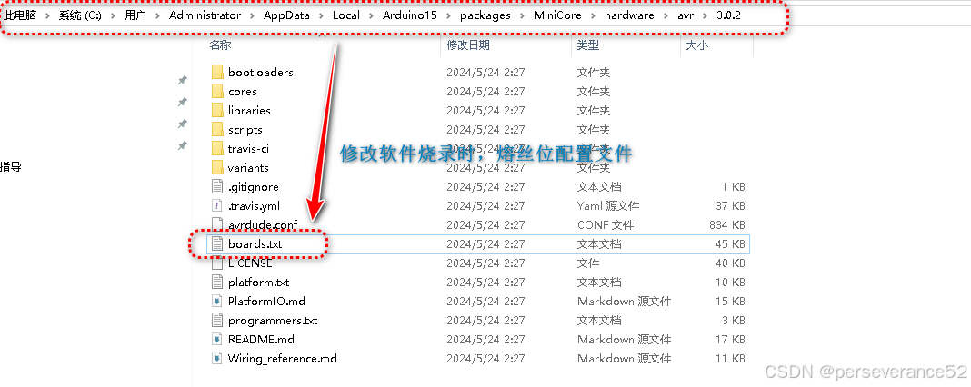
针对Arduino IDE +AVR烧录工具(AVRISP/USBASP)自动烧录熔丝位修改
🎉在使用Arduino IDE配合烧录工具(AVRISP/USBASP),烧录时,熔丝位是附带自动烧录的,在选择使用
MiniCore固件,烧录Bootloader程序时,默认配置的高熔丝位为:0xD7,明显是不合理的,我们需要手动去修改。
-
🔧文件修改位置:
boards.txt
-
找到对应位置:修改成
0xde或者0xda
-
修改过,关闭Arduino IDE ,程序打开,烧录Bootloader程序:
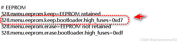
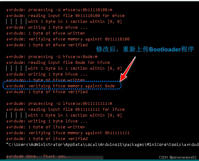
- 👉高熔丝位如果配置为
0xd7,不是不能用,只是在平时做程序烧录过程中,容易出现无法连接上目标的问题。- 🎉出现无法连接目标的原因个人分析:IDE发出程序烧录命令,到MCU接收到指令后,MCU执行复位,MCU从地址0x00(BOOTRST=0)开始运行,运行到bootloader程序地址,这个过程可能会错过下载。
-(BOOTRST=1),MCU执行复位,MCU直接从bootloader地址执行开始运行。
📝通过命令行指令烧录
- 🌿通过 命令行进行熔丝位配置,使用的是usbasp烧录器,前提是安装了Arduino IDE,其他型号也可以通过此命令实现对目标型号芯片进行熔丝位配置:(直接在cmd命令提示符窗口内使用)
C:\Users\Administrator\AppData\Local\Arduino15\packages\arduino\tools\avrdude\6.3.0-arduino17/bin/avrdude -CC:\Users\Administrator\AppData\Local\Arduino15\packages\arduino\tools\avrdude\6.3.0-arduino17/etc/avrdude.conf -v -patmega328pb -cusbasp -Pusb -e -Ulock:w:0xFF:m -Uefuse:w:0xFF:m -Uhfuse:w:0xDE:m -Ulfuse:w:0xFF:m
- 🌿使用Polulo支持包固件下的bootloader.hex固件,使用命令行烧录bootloader命令:(直接在cmd命令提示符窗口内使用)
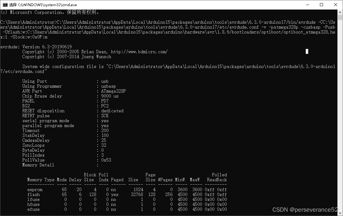
C:\Users\Administrator\AppData\Local\Arduino15\packages\arduino\tools\avrdude\6.3.0-arduino17/bin/avrdude -CC:\Users\Administrator\AppData\Local\Arduino15\packages\arduino\tools\avrdude\6.3.0-arduino17/etc/avrdude.conf -v -patmega328pb -cusbasp -Pusb -Uflash:w:C:\Users\Administrator\AppData\Local\Arduino15\packages\pololu-a-star\hardware\avr\5.1.0/bootloaders/optiboot/optiboot_atmega328pb_16mhz.hex:i -Ulock:w:0xCF:m
- 🌿使用MiniCore支持包固件下的bootloader.hex固件,使用命令行烧录bootloader命令:
C:\Users\Administrator\AppData\Local\Arduino15\packages\MiniCore\tools\avrdude\7.2-arduino.1/bin/avrdude -CC:\Users\Administrator\AppData\Local\Arduino15\packages\MiniCore\hardware\avr\3.0.1/avrdude.conf -v -patmega328pb -cusbasp -e -Ulock:w:0xff:m -Uefuse:w:0b11110101:m -Uhfuse:w:0xd7:m -Ulfuse:w:0b11111111:m
-
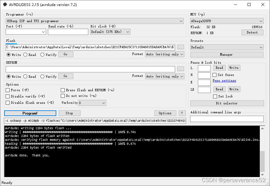
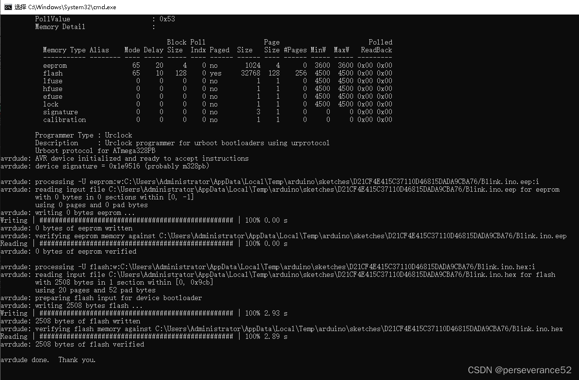
- 🔖带eep烧录程序命令演示:(需要定位到avrdude路径下)
avrdude -C"C:\Users\Administrator\AppData\Local\Arduino15\packages\MiniCore\hardware\avr\3.0.1/avrdude.conf" -v -patmega328pb -curclock -PCOM6 -b9600 -D -xnometadata "-Ueeprom:w:C:\Users\Administrator\AppData\Local\Temp\arduino\sketches\D21CF4E415C37110D46815DADA9CBA76/Blink.ino.eep:i" -Uflash:w:"C:\Users\Administrator\AppData\Local\Temp\arduino\sketches\D21CF4E415C37110D46815DADA9CBA76/Blink.ino.hex:i"
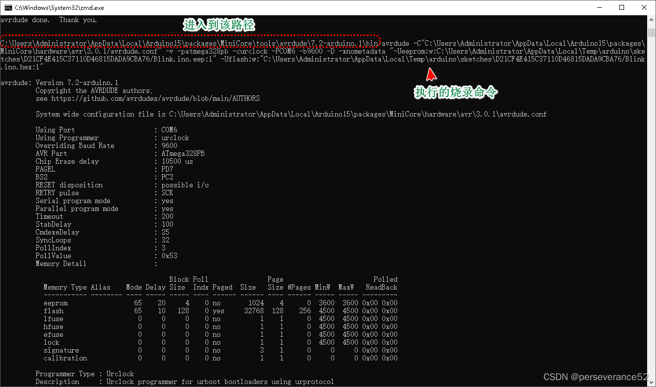
烧录过程和结果:
-
- 🔖不带eep烧录命令:(需要定位到avrdude路径下)
avrdude -C"C:\Users\Administrator\AppData\Local\Arduino15\packages\MiniCore\hardware\avr\3.0.1/avrdude.conf" -v -patmega328pb -curclock -PCOM6 -b9600 -D -xnometadata -Uflash:w:"C:\Users\Administrator\AppData\Local\Temp\arduino\sketches\D21CF4E415C37110D46815DADA9CBA76/Blink.ino.hex:i"
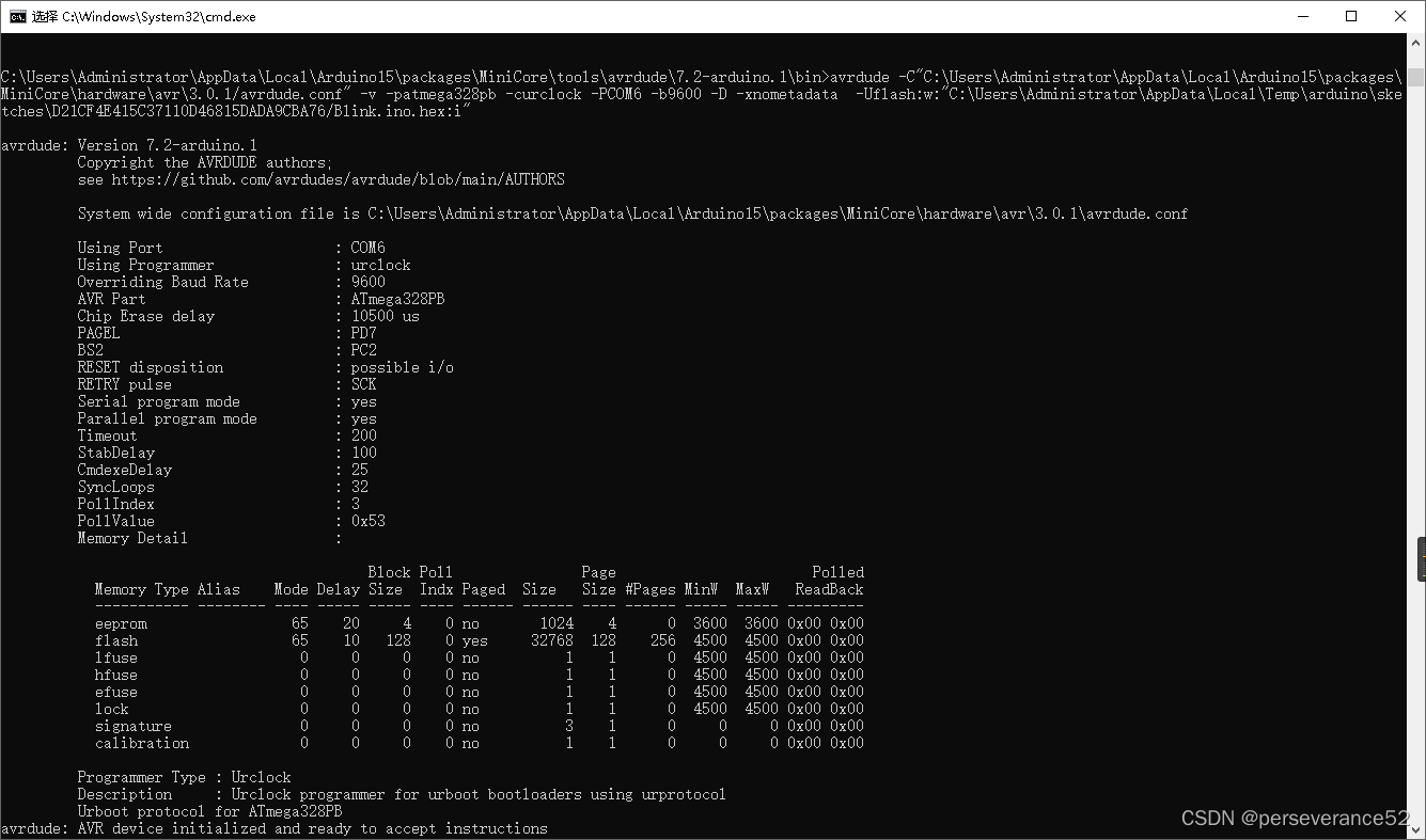
烧录结果:

使用命令行烧录
- 模拟Arduino IDE上传代码指令:
- Arduino IDE上传指令:
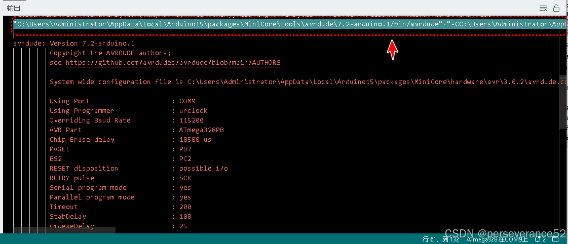
"C:\Users\Administrator\AppData\Local\Arduino15\packages\MiniCore\tools\avrdude\7.2-arduino.1/bin/avrdude" "-CC:\Users\Administrator\AppData\Local\Arduino15\packages\MiniCore\hardware\avr\3.0.2/avrdude.conf" -v -V -patmega328pb -curclock -PCOM9 -b115200 -D -xnometadata "-Ueeprom:w:C:\Users\Administrator\AppData\Local\Temp\arduino\sketches\B5ED64EE1DF3597F2BECBA5D5289F9E7/External_Interrupt.ino.eep:i" "-Uflash:w:C:\Users\Administrator\AppData\Local\Temp\arduino\sketches\B5ED64EE1DF3597F2BECBA5D5289F9E7/External_Interrupt.ino.hex:i"
- 🔖提取其中的指令,进行CMD单独烧录:
avrdude -C avrdude.conf -v -V -patmega328pb -curclock -PCOM9 -b115200 -D -xnometadata "-Uflash:w:D:\Arduino_Project\External_Interrupt\build\MiniCore.avr.328\External_Interrupt.ino.hex:i"
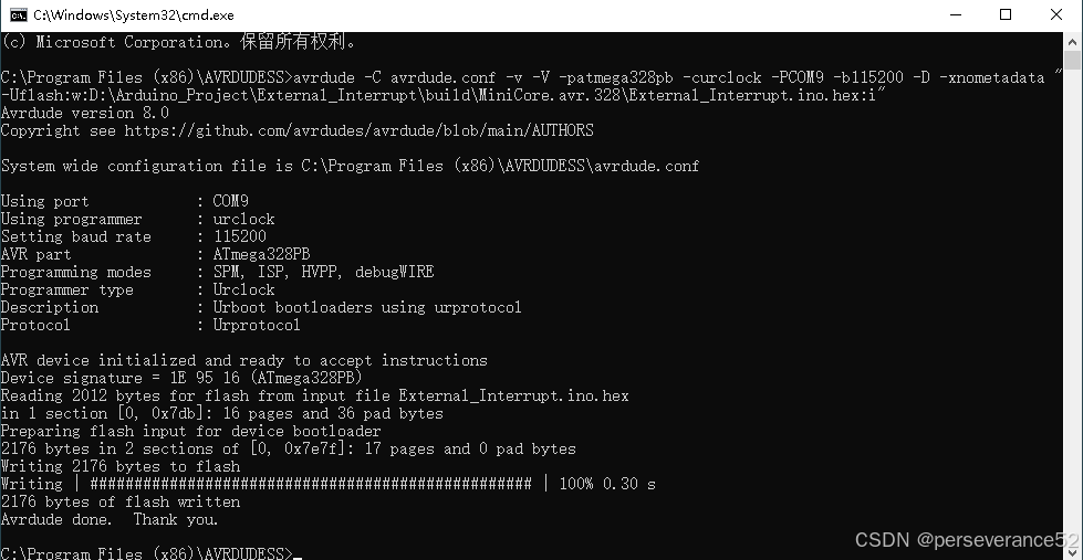
- 其中:
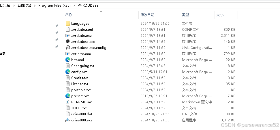
avrdude -C avrdude.conf -v -V
需要指定文件位置,这里我使用的是AVRDUDESS软件文件夹目录:
串口下载功能实现基本要素
-
- 需要提前下载Bootloader程序。
-
- MCU熔丝位,一点需要配置正确,这里的说的熔丝位特指:熔丝高位(H)
- MCU熔丝位,一点需要配置正确,这里的说的熔丝位特指:熔丝高位(H)
- 其中的
BOOTAZ1和BOOTSZ0,有bootloader程序容量自身决定的,BOOTRST位,如果烧录了bootloader程序,该位最好配置为1.
📑AVRDude 命令参数说明
-C:指定 AVRDude 配置文件的路径。
-v:显示详细信息,便于调试。
-V:关闭验证。
-p:指定目标芯片型号,这里是 atmega328pb。
-P:指定要使用的串口,例如 COM9。
-b:设置波特率,这里为 115200。
-D:禁止擦除芯片。
-xnometadata:禁止写入元数据。
-U:用于指定需要烧录的内存类型(eeprom 和 flash),w 表示写入,后跟文件路径。
"C:\Users\Administrator\AppData\Local\Arduino15\packages\MiniCore\tools\avrdude\7.2-arduino.1/bin/avrdude" -C"C:\Users\Administrator\AppData\Local\Arduino15\packages\MiniCore\hardware\avr\3.0.2/avrdude.conf" -v -V -patmega328pb -curclock -PCOM9 -b115200 -D -xnometadata "-Ueeprom:w:C:\Users\Administrator\AppData\Local\Temp\arduino\sketches\B5ED64EE1DF3597F2BECBA5D5289F9E7/External_Interrupt.ino.eep:i" "-Uflash:w:C:\Users\Administrator\AppData\Local\Temp\arduino\sketches\B5ED64EE1DF3597F2BECBA5D5289F9E7/External_Interrupt.ino.hex:i"
- 🔖此文章仅作为个人学习探索知识的总结,不作为他人或引用者的理论依据,由于学识所限,难免会出现错误或纰漏,欢迎大家指正。
版权声明:本文内容由互联网用户自发贡献,该文观点仅代表作者本人。本站仅提供信息存储空间服务,不拥有所有权,不承担相关法律责任。如发现本站有涉嫌侵权/违法违规的内容, 请发送邮件至 举报,一经查实,本站将立刻删除。
如需转载请保留出处:https://bianchenghao.cn/bian-cheng-ji-chu/84739.html