对应示例程序:
segment_wedge_bonds.hdev
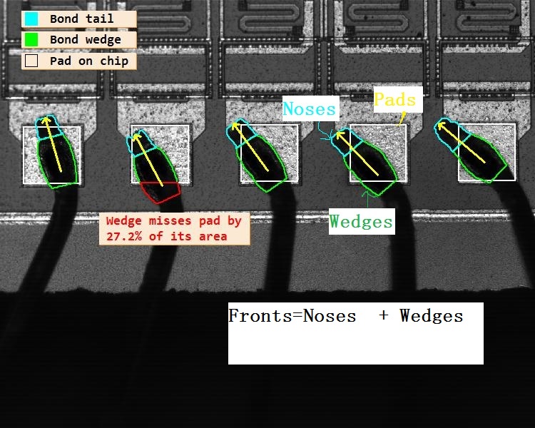
目标:检测球键在焊盘上的方向 以及覆盖率
思路为:
1.窗口初始化
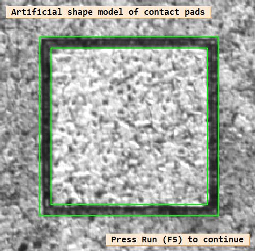
2.利用先验知识,生成一个内外框矩形作为XLD匹配模板,用来寻找焊盘
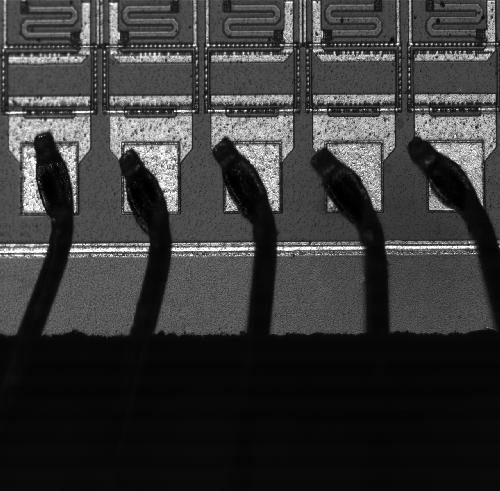
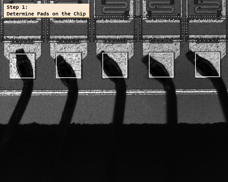
3.读入图像,利用阈值分割,将黑色的引线部分提取出来,并利用算子line_gauss检测出图中含有的曲线,对其进行适当膨胀,用来扩大范围。借助步骤2中的匹配模板,定位焊盘
4.对焊盘区域进行适当膨胀放大,计算其与膨胀曲线的交集,其实就是取引线与焊盘连接的那部分图像
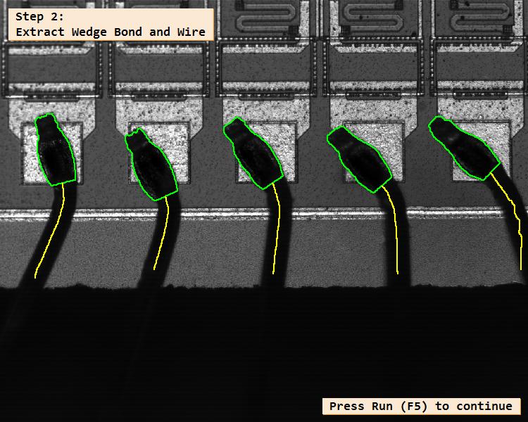
5.通过阈值分割,填充孔洞,形态学等手段,将与焊盘相连相近的那部分区域提取出来,称为Contacts,如果再把直线得到的曲线合并在一起,就相当于提取出了整个引线
6.通过圆形开操作,最小包围矩形等把与焊盘直接相连的那部分圆弧较大的区域提取出来,称为球键/楔键 (Wedges ) 。球键与焊盘的图像做差,得出的就是不在焊盘上的球键面积,可以用来计算整个球键覆盖比和缺失比。
7.通过求差,临近边缘距离等手段,将球键与引线的最上面的部分(Noses)合并在一起,统称为Fronts。如果再将之前提取出的曲线 合并
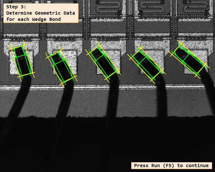
8.计算Fronts的面积 等效椭圆 方向等 从而生成一个箭头XLD轮廓,用来标识方向。同时,也利用直线段将noses 和 Fronts 进行标识
9.在计算步骤6提到的面积比时,因为在图像中存在多个球键,多个可能不合格的球键,事先并不知道一一对应关系,因此可以利用不合格区域 与 球键的重复面积 进行定位,从而计算二者的面积比例。
图像:
根据先验知识,生成的XLD匹配模板,绿色内外框矩形
* 原图:
* 焊盘定位(Pads)
* 提取球键和引线
* 可视化
* 测量结果:
代码:
//检测球键在焊盘上的方向 以及覆盖率
//初始化
dev_update_off ()
dev_set_draw ('margin')
*
* Create shape model for contact pads from artificial contours.
*从人工轮廓创建接触垫形状模型
//先根据先验知识,人为的确定一个内外框矩形 然后设为XLD模板轮廓,再读入一个焊盘图像进行匹配查找 定位焊盘
gen_rectangle2_contour_xld (OuterRectangle, 0, 0, 0, 77, 77)     //外框
gen_rectangle2_contour_xld (InnerRectangle, 0, 0, 0, 67.5, 67.5)  //内框
concat_obj (InnerRectangle, OuterRectangle, ModelContours)      //合并为一个包含内外框的元组

create_shape_model_xld (ModelContours, 'auto', 0, 0, 'auto', 'auto', 'ignore_local_polarity', 5, PadModelID)  //创建一个XLD模型
read_image (Model, 'bonds/wedge_bond_chip_model')
find_shape_model (Model, PadModelID, 0, 0, 0.5, 1, 0.5, 'least_squares', 0, 0.9, Row, Column, Angle, Score)
vector_angle_to_rigid (0, 0, 0, Row, Column, 0, HomMat2D)
set_shape_model_metric (Model, PadModelID, HomMat2D, 'use_polarity')
*
dev_close_window ()
dev_open_window_fit_image (Model, 0, 0, -1, -1, WindowHandle)
set_display_font (WindowHandle, 16, 'mono', 'true', 'false')
dev_display (Model)
dev_set_line_width (2)
disp_message (WindowHandle, 'Artificial shape model of contact pads', 'window', -1, -1, 'black', 'true')
dev_display_shape_matching_results (PadModelID, 'green', Row, Column, Angle, 1.0, 1.0, 0)
disp_continue_message (WindowHandle, 'black', 'true')
stop ()
* 在wegde键合过程之后,每一个键合都会在尺寸和定位方面进行测试
StringIntro := ['After the wegde bonding process\neach bond is tested in terms of\ndimension and positioning','Inspection of chip with\nwedge bonding']
*
hom_mat2d_identity (HomMat2DIdentity)
NumImages := 10
for Index := 1 to NumImages by 1
    read_image (Image, 'bonds/wedge_bond_chip_' + Index$'02')   //读入待测图像
    *
     //步骤1:先定位焊盘
    * Extraction of wires. It relies on the operator lines_gauss()
    * Since extracting lines is computationally expensive, we first
    * segment the areas of interest, in order to speed up the process.
    *拔取焊线。它依赖于算符lines_gauss(),因为提取直线的计算成本很高,我们首先对感兴趣的区域进行分割,以加快处理速度。
    zoom_image_factor (Image, ImageZoomed, 0.1, 0.1, 'weighted')   //缩小
    * Segment the dark areas containing the wires and contacts
    threshold (ImageZoomed, Dark, 0, 50)   //阈值分割 引线是黑色的 因此阈值是0到50
    closing_circle (Dark, RegionClosing, 3.5)   //圆形闭操作  去掉干扰成分  连接断裂轮廓

    reduce_domain (ImageZoomed, RegionClosing, ImageReduced)   //扣出包含引线的图像
    calculate_lines_gauss_parameters (8, 80, Sigma, Low, High)  //计算Gauss参数 用于检测线条
    lines_gauss (ImageReduced, Lines, Sigma, Low, High, 'dark', 'true', 'true', 'true')  //检测出引线

    select_contours_xld (Lines, SelectedContours, 'contour_length', 15, 200, -0.5, 0.5)  //对引线进行参数筛选
    * Scale the extracted contours back into the original image
    *将提取的轮廓缩放回原始图像
    hom_mat2d_scale (HomMat2DIdentity, 10, 10, 0, 0, HomMat2DScale)
    affine_trans_contour_xld (SelectedContours, ContoursAffinTrans, HomMat2DScale)
    contours_neighborhood_regions (ContoursAffinTrans, WireNeighborhood, WireRegions, 48)  //对提取出的引线进行适当膨胀 扩大区域 方便后面的裁剪
    reduce_domain (Image, WireNeighborhood, ImageReduced2)  //裁剪出含有引线的图像
    find_pads_in_image (ImageReduced2, InnerRectangle, Pads, PadModelID)  //根据之前创建的模型 定位Pad(焊盘?具体名字不太清楚)
    *
    * Extract wires more precisely
    *更精确地提取导线
     步骤2:提取楔键和导线
    dilation_rectangle1 (Pads, RegionDilation, 140, 140)  //Pad进行膨胀
    intersection (RegionDilation, WireNeighborhood, RegionIntersection)  //计算Pad膨胀后的区域 与  引线膨胀后的区域   的交集
    //上面就是再细化一下  把引线与焊盘接触的区域  进行进一步的定位
    reduce_domain (Image, RegionIntersection, ImageReduced) //裁剪出来
    threshold (ImageReduced, Region, 0, 40)  //阈值分割 提取引线

    fill_up (Region, RegionFillUp)  //填充孔洞  保证引线内部区域是均匀的
    opening_circle (RegionFillUp, RegionOpening, 5.5)  //圆形开操作 去掉周围零碎的小区域
    //根据上诉两个操作 得到干净的引线区域
    connection (RegionOpening, Contacts) //将区域分开
    count_obj (Contacts, NContacts)     //统计数目
    *
    * Examine the position and orientation the wedge bonds
    *检查楔键的位置和方向
    opening_circle (Contacts, RegionOpening, 32)  //较大参数的圆形开操作  定位到中间部分 相对圆弧的区域
    smallest_rectangle2 (RegionOpening, Row, Column, Phi, Length1, Length2)  //最小外包矩形
    gen_rectangle2 (Rectangle1, Row, Column, Phi, Length1 - 20, Length2)
    intersection (Rectangle1, RegionOpening, Wedges)  //外包矩形 与  RegionOpening 的交集  作为楔键的位置

    difference (Wedges, Pads, OuterParts)   //将楔键  与 焊盘 做差 得到超出 焊盘区域的楔键面积


    select_shape (OuterParts, OuterParts, 'area', 'and', 2000, 99999)  //筛选较大的面积

    difference (Contacts, Wedges, WireRest)  //引线  与  楔键 做差   得到除楔键以外的  区域

    connection (WireRest, ConnectedRegions) //分开上述区域单独处理

    select_shape_proto (ConnectedRegions, RegionDilation, Candidates, 'distance_contour', 1, 100)
    //判断Regions中每个region的边缘距离Pattern边缘的距离,Min和Max控制距离的下限和上限
    select_shape (Candidates, Noses, 'area', 'and', 2000, 4500)

    //上面的步骤 提取出了和 楔键 相连的焊条上方区域
    union2 (Noses, Wedges, Fronts)   //将楔键 与 上面的引线合并 作为 Fronts
    union1 (Fronts, Fronts)


    //步骤3:确定每个楔键的几何数据
    connection (Fronts, Fronts)  //5个Fronts分开
    gen_wedge_arrow (Fronts, Arrows)  //计算Fronts的面积  等效椭圆 方向等 从而生成一个箭头XLD轮廓
    difference (WireRegions, Fronts, WireCenterRests)  //计算Fronts  与之前得到的引线的差异  其实就是把引线 与 Fronts 合并在一起
    *
    * Display results
    //显示结果
    dev_resize_window_fit_image (Image, 0, 0, -1, -1)
    if (Index < 3)  //前3幅图  进行步骤说明  后续直接运行 去掉提示
        dev_display (Image)
        //在wegde键合过程之后,每个键都会在尺寸和位置方面进行测试
        disp_message (WindowHandle, StringIntro[min([Index - 1,1])], 'window', 12, 12, 'black', 'true')
        disp_continue_message (WindowHandle, 'black', 'true')
        stop ()
        dev_display (Image)
        dev_set_line_width (2)
        dev_set_color ('white')
        dev_display (Pads)  //显示焊盘


        disp_message (WindowHandle, 'Step 1:\nDetermine Pads on the Chip', 'window', 12, 12, 'black', 'true')
        disp_continue_message (WindowHandle, 'black', 'true')
        stop ()
        dev_display (Image)
        dev_set_line_width (2)
        dev_set_color ('green')
        dev_display (Fronts)  //显示Fronts
        dev_set_color ('yellow')
        dev_display (WireCenterRests)

        disp_message (WindowHandle, 'Step 2:\nExtract Wedge Bond and Wire', 'window', 12, 12, 'black', 'true')
        disp_continue_message (WindowHandle, 'black', 'true')

        StringGeomtericData := 'Step 3:\nDetermine Geometric Data\nfor each Wedge Bond'
        stop ()
    else
        dev_display (Image)
        disp_message (WindowHandle, StringIntro[1], 'window', 12, 12, 'black', 'true')
        wait_seconds (0.4)
        dev_set_line_width (2)
        dev_set_color ('white')
        dev_display (Pads)
        wait_seconds (0.4)
        dev_display (Image)
        disp_message (WindowHandle, StringIntro[1], 'window', 12, 12, 'black', 'true')
        dev_set_line_width (2)
        dev_set_color ('green')
        dev_display (Fronts)
        dev_set_color ('yellow')
        dev_display (WireCenterRests)
        wait_seconds (0.4)
        StringGeomtericData := StringIntro[1]
    endif
    *
    * Geometric data
    dev_display (Image)
    dev_set_line_width (2)
    dev_set_color ('green')
    dev_display (Fronts)
    dev_set_color ('yellow')
    dev_display_geometric_data (Fronts, Noses, GeometricData)  //用直线段  把Fronts区域 和 Noses区域  框出来 主要用来可视化

    disp_message (WindowHandle, StringGeomtericData, 'window', 12, 12, 'black', 'true')
    disp_continue_message (WindowHandle, 'black', 'true')
    stop ()
    * Evaluation of results

    dev_display (Image)
    dev_set_color ('white')
    dev_display (Pads)
    dev_set_color ('green')
    dev_set_draw ('margin')
    dev_display (Wedges)
    dev_set_color ('red')
    dev_display (OuterParts)
    dev_set_color ('cyan')
    dev_display (Noses)
    dev_set_color ('yellow')
    dev_set_line_width (3)
    dev_display (Arrows)
    dev_display_caption (OuterParts, Fronts, WindowHandle)  //先根据不合格的区域  跟哪个Front重叠 定位到不合格的焊盘  再计算二者的面积比
    if (Index < 3)
        disp_message (WindowHandle, 'Step 4:\nEvaluate results of\nwedge bond inspection', 'window', 12, 300, 'black', 'true')
    endif
    *
    if (Index < NumImages)
        disp_continue_message (WindowHandle, 'black', 'true')
        stop ()
    endif
endfor
clear_shape_model (PadModelID)  //清除模型  实际使用中要牢记
用到的几个算子:
create_shape_model_xld–创建一个XLD匹配模板
find_shape_model–在图像中查找形状模型的最佳匹配项
lines_gauss–检测线条及其宽度
smallest_rectangle2–最小外包矩形
gen_arrow_contour_xld–生成一个箭头XLD
difference–求两幅图像的差异
fill_up –填补图像中的孔洞
select_shape_proto –选择彼此有一定关系的区域
参考资料:
[1].https://www.cnblogs.com/xh6300/p/6648435.html
今天的文章二维测量–球键的视觉检测–方向和覆盖率分享到此就结束了,感谢您的阅读。
版权声明:本文内容由互联网用户自发贡献,该文观点仅代表作者本人。本站仅提供信息存储空间服务,不拥有所有权,不承担相关法律责任。如发现本站有涉嫌侵权/违法违规的内容, 请发送邮件至 举报,一经查实,本站将立刻删除。
如需转载请保留出处:https://bianchenghao.cn/59820.html
